137
Detailed Repair Procedures
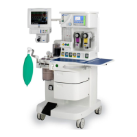
5. Remove the 8 mm tubing, indicated in Figure 94, that is routed to the fl ow
sensor block assembly.
Figure 94 - Location of 8 mm Tubing
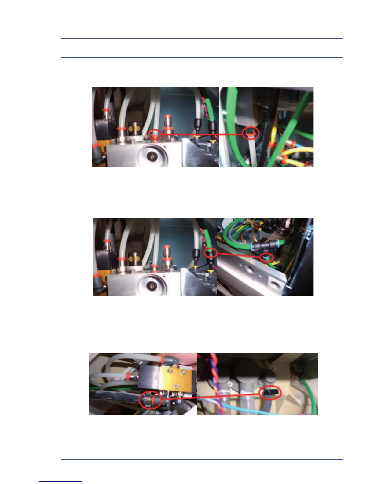
6. Remove the 6 mm tubing from the top 4-6 mm increaser routed to the
8 mm/6 mm tee.
Figure 95 - Location of 6 mm Tubing
7. Remove the 8mm stem clamped to the fresh gas hose routed to the
absorber manifold.
Figure 96 - Location of 8 mm Stem