73
System Checks
5. Connect a 22 mm reusable tube to the tee piece routed to the AGSS
auxiliary port. (Note: If the machine is fi tted with an ACGO, ensure that
the switch is set to ACGO.)
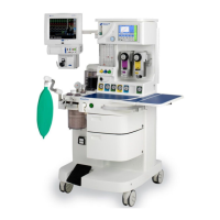
Figure 22 - Connect O
2
Analyzer (L) and Tubing to AGSS (R)
6. Turn the power switch to the “ON” position.
7. Ensure that the fl owmeter backlight is on. (for non-EFM machines only)
8. Ensure minimum O
2
fl ow is between 130 – 170 ml.
9. Set a fl ow of 1 L/min on the N
2
O fl ow control valve. Verify the O
2
analyzer
reads between 21-30%. (Note: The O
2
fl ow will increase as the N
2
O fl ow
is increased)
10. Set a fl ow of 6 L/min on the N
2
O fl ow control valve. Verify the O
2
analyzer
reads between 21-30%.
11. Set a fl ow of 12 L/min on the N
2
O fl ow control valve. Verify the O
2
analyzer reads between 21-35%.
12. Set the fl ow on the O
2
fl ow control valve down to 3 L/min. Verify that
the O
2
analyzer reads between 21-30%. (Note: when the O
2
fl ow is
decreased, the N
2
O fl ow will also decrease.)
13. Decrease the O
2
fl ow to 1.5 L/min. Verify that the O
2
analyzer reads
between 21-30%.
14. Decrease the O
2
fl ow to 0.4L/min. Verify that the O
2
analyzer reads
between 21-30%.