131
4. The block is held in place by three M5 screws. Remove these screws and
withdraw the block from the machine.
5. Replacement is the reverse of this procedure.
5.9 Alarm Block Removal/Replacement
5.9.1 On units Manufactured Before Feb 2009
1. Remove the rear cover (see section 5.1).
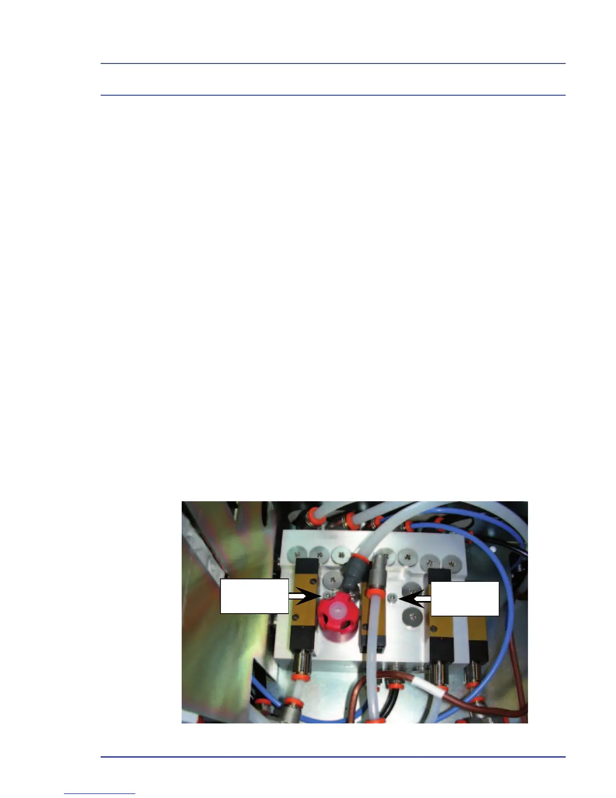
2. Remove the two M4 fi xing screws from the alarm block.
3. The positions of each pipe entering the block should now be marked
clearly on each fi tting and the relevant pipe (use masking tape or a
marker pen), the removal of the fi xing screws will allow the block to
be moved slightly for access to some of the pipes. Once all pipes and
connections are clearly marked (the different gases are also diameter
indexed) the pipes may be disconnected and the block removed.
4. The replacement block will require the transfer of the fi ttings and blanking
plugs from the old block to the same positions on the new block. This
should be done one item at a time and their positions checked carefully.
Once the fi ttings have been transferred, the block can be reconnected
and the fi xing screws replaced.
5. Carry out function test on alarm (see section 3.2.2).
Detailed Repair Procedures
Figure 86 - Alarm Block Removal (up to Feb 2009)
Fixing
Screw 2
Fixing
Screw 1