DocID13902 Rev 15 1070/1128
RM0008 Debug support (DBG)
1100
31.2 Reference ARM
®
documentation
• Cortex
®
-M3 r1p1 Technical Reference Manual (TRM)
It is available from:
http://infocenter.arm.com/help/topic/com.arm.doc.ddi0337e/DDI0337E_cortex_m3_r1p
1_trm.pdf
• ARM
®
Debug Interface V5
• ARM
®
CoreSight Design Kit revision r1p1 Technical Reference Manual
31.3 SWJ debug port (serial wire and JTAG)
The core of the STM32F10xxx integrates the Serial Wire / JTAG Debug Port (SWJ-DP). It is
an ARM
®
standard CoreSight debug port that combines a JTAG-DP (5-pin) interface and a
SW-DP (2-pin) interface.
• The JTAG Debug Port (JTAG-DP) provides a 5-pin standard JTAG interface to the
AHP-AP port.
• The Serial Wire Debug Port (SW-DP) provides a 2-pin (clock + data) interface to the
AHP-AP port.
In the SWJ-DP, the two JTAG pins of the SW-DP are multiplexed with some of the five JTAG
pins of the JTAG-DP.
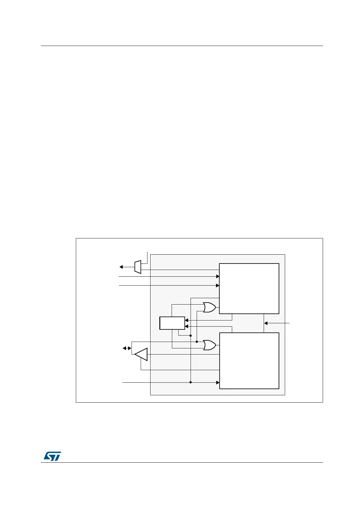
Figure 361. SWJ debug port
Figure 361 shows that the asynchronous TRACE output (TRACESWO) is multiplexed with
TDO. This means that the asynchronous trace can only be used with SW-DP, not JTAG-DP.
TRACESWO
JTDO
JTDI
NJTRST
nTRST
TDI
TDO
SWJ-DP
TDO
TDI
nTRST
TCK
TMS
nPOTRST
JTAG-DP
nPOTRST
From
power-on
reset
DBGRESETn
DBGDI
DBGDO
DBGDOEN
DBGCLK
SW-DP
SWCLKTCK
SWDOEN
SWDO
SWDITMS
SWD/JTAG
select
JTMS/SWDIO
JTCK/SWCLK
(asynchronous trace)
ai17139
 Loading...


