Analog-to-digital converter (ADC) RM0008
223/1128 DocID13902 Rev 15
(digital word) is calculated for each capacitor, and during all subsequent conversions, the
error contribution of each capacitor is removed using this code.
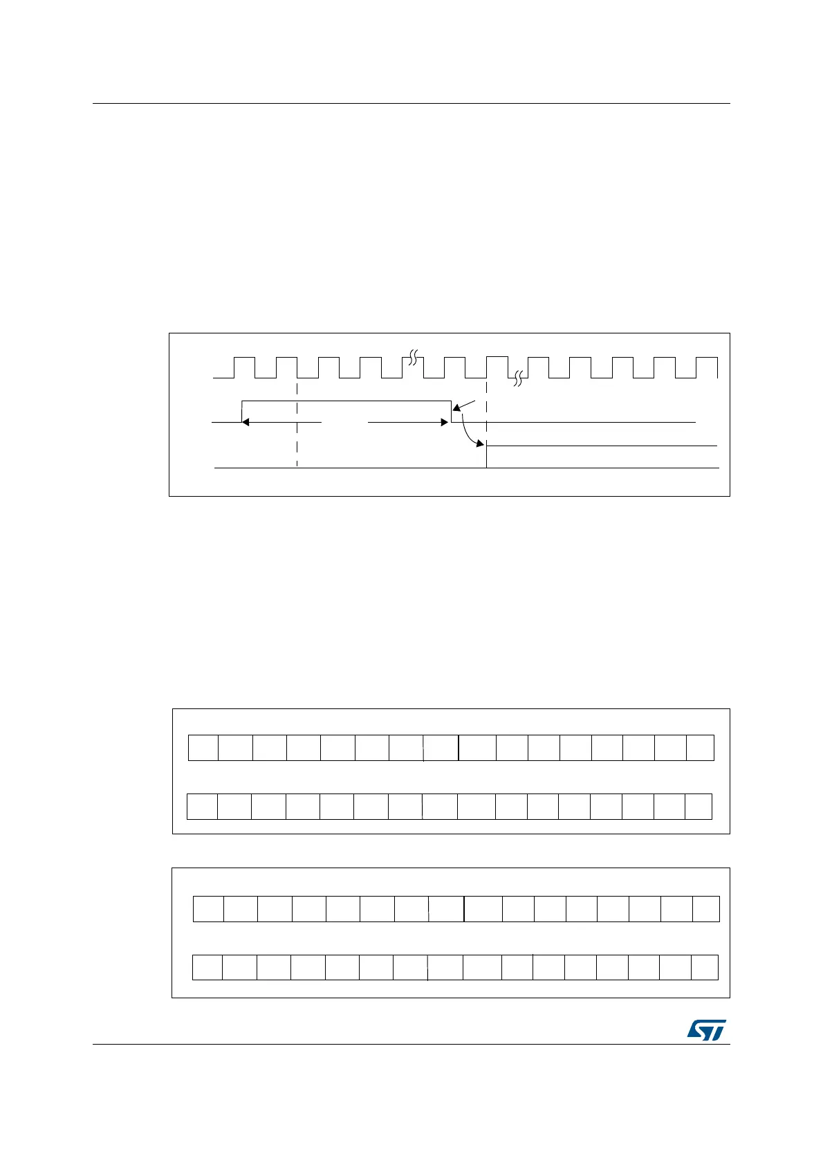
Calibration is started by setting the CAL bit in the ADC_CR2 register. Once calibration is
over, the CAL bit is reset by hardware and normal conversion can be performed. It is
recommended to calibrate the ADC once at power-on. The calibration codes are stored in
the ADC_DR as soon as the calibration phase ends.
Note: It is recommended to perform a calibration after each power-up.
Before starting a calibration, the ADC must have been in power-on state (ADON bit = ‘1’) for
at least two ADC clock cycles.
Figure 26. Calibration timing diagram
11.5 Data alignment
ALIGN bit in the ADC_CR2 register selects the alignment of data stored after conversion.
Data can be left or right aligned as shown in Figure 27. and Figure 28.
The injected group channels converted data value is decreased by the user-defined offset
written in the ADC_JOFRx registers so the result can be a negative value. The SEXT bit is
the extended sign value.
For regular group channels no offset is subtracted so only twelve bits are significant.
Figure 27. Right alignment of data
Figure 28. Left alignment of data
CLK
t
CAL
Calibration ongoing
CAL
ADC
Conversion
Normal ADC Conversion
Calibration Reset by Hardware
D7D8 D9 D6 D5 D4 D3 D2 D1 D0 D10 D11 SEXT SEXT SEXT SEXT
D7D8 D9 D6 D5 D4 D3 D2 D1 D0 D10 D11
Injected group
Regular group
0000
SEXT D0 D1D11 D10 D9 D8 D7 D6 D5 D2 D3 D4 0 0 0
D0 D1D11 D10 D9 D8 D7 D6 D5 D2 D3 D4 0 0 00
Injected group
Regular group
 Loading...


