DocID13902 Rev 15 722/1128
RM0008 Serial peripheral interface (SPI)
742
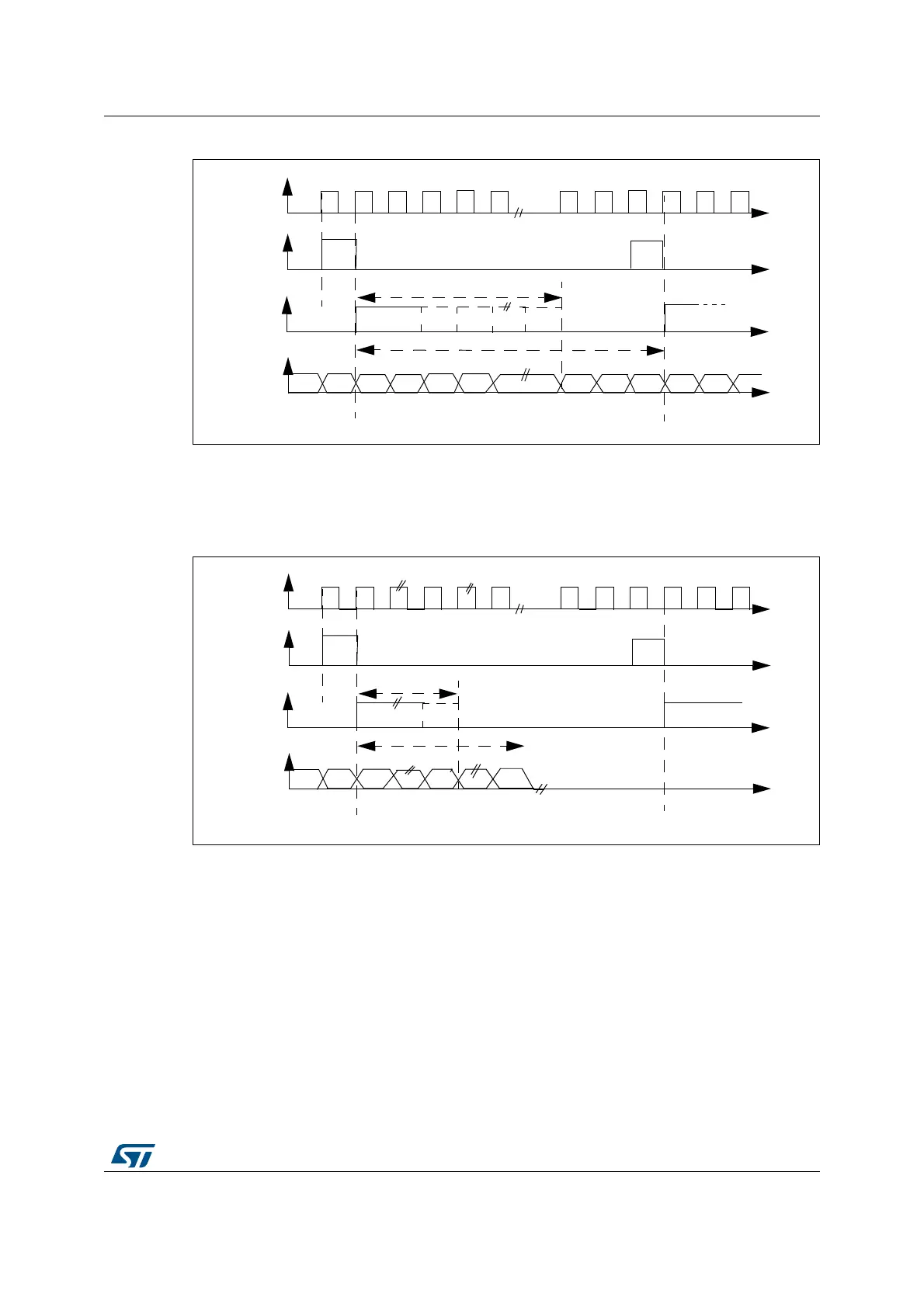
Figure 264. PCM standard waveforms (16-bit)
For long frame synchronization, the WS signal assertion time is fixed 13 bits in master
mode.
For short frame synchronization, the WS synchronization signal is only one cycle long.
Figure 265. PCM standard waveforms (16-bit extended to 32-bit packet frame)
Note: For both modes (master and slave) and for both synchronizations (short and long), the
number of bits between two consecutive pieces of data (and so two synchronization signals)
needs to be specified (DATLEN and CHLEN bits in the SPI_I2SCFGR register) even in
slave mode.
25.4.3 Clock generator
The I
2
S bitrate determines the dataflow on the I
2
S data line and the I
2
S clock signal
frequency.
I
2
S bitrate = number of bits per channel × number of channels × sampling audio frequency
For a 16-bit audio, left and right channel, the I
2
S bitrate is calculated as follows:
I
2
S bitrate = 16 × 2 × F
S
MSB
LSB
MSB
CK
WS
SD
16-bit
WS
fixed to 13-bit
short
frame
long
frame
MSB
CK
WS
SD
16-bit
WS
fixed to 13-bit
short
frame
long
frame
LSB
 Loading...


