DocID13902 Rev 15 382/1128
RM0008 General-purpose timers (TIM2 to TIM5)
417
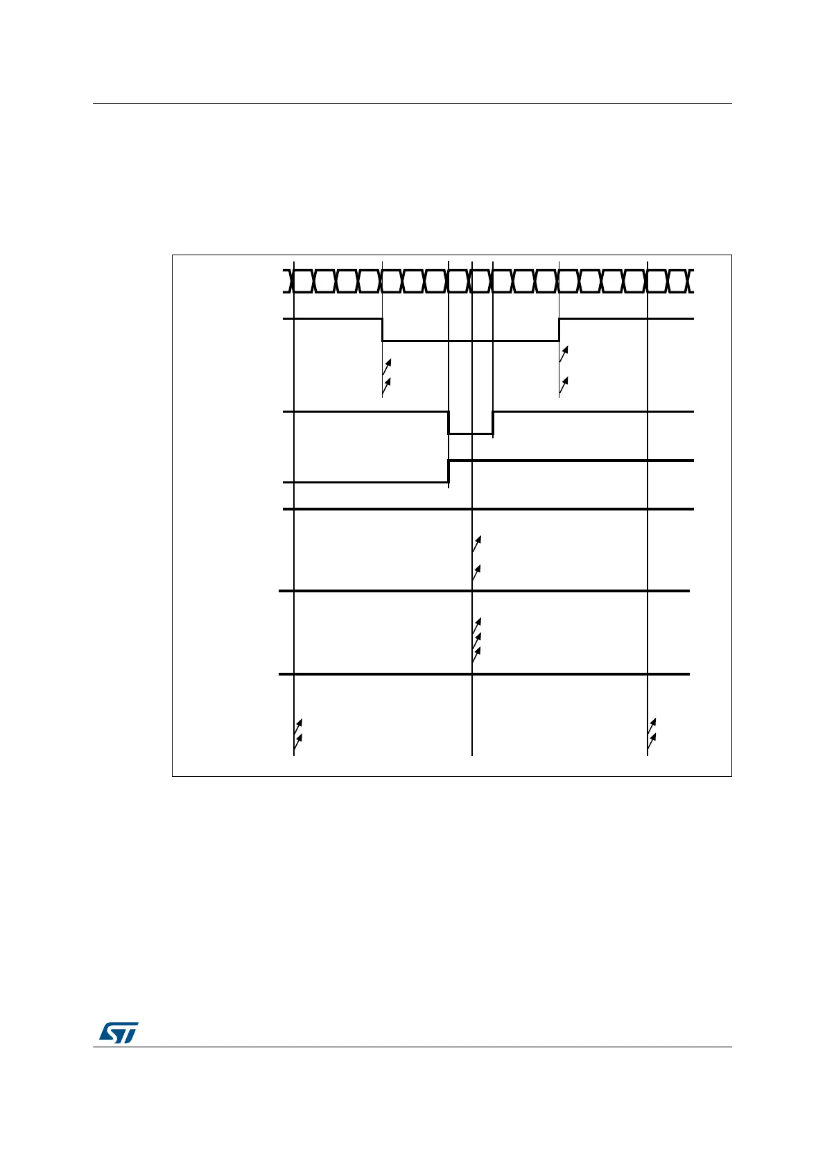
Figure 131 shows some center-aligned PWM waveforms in an example where:
• TIMx_ARR=8,
• PWM mode is the PWM mode 1,
• The flag is set when the counter counts down corresponding to the center-aligned
mode 1 selected for CMS=01 in TIMx_CR1 register.
Figure 131. Center-aligned PWM waveforms (ARR=8)
Hints on using center-aligned mode:
• When starting in center-aligned mode, the current up-down configuration is used. It
means that the counter counts up or down depending on the value written in the DIR bit
##X)&
#OUNTERREGISTER
##2X
/#X2%&
#-3
#-3
#-3
##X)&
##2X
/#X2%&
#-3OR
##X)&
##2X
/#X2%&
#-3
#-3
#-3
gg
##X)&
##2X
/#X2%&
#-3
#-3
#-3
gg
##X)&
##2X
/#X2%&
#-3
#-3
#-3
gg
AIB
 Loading...


