DocID13902 Rev 15 134/1128
RM0008 Connectivity line devices: reset and clock control (RCC)
158
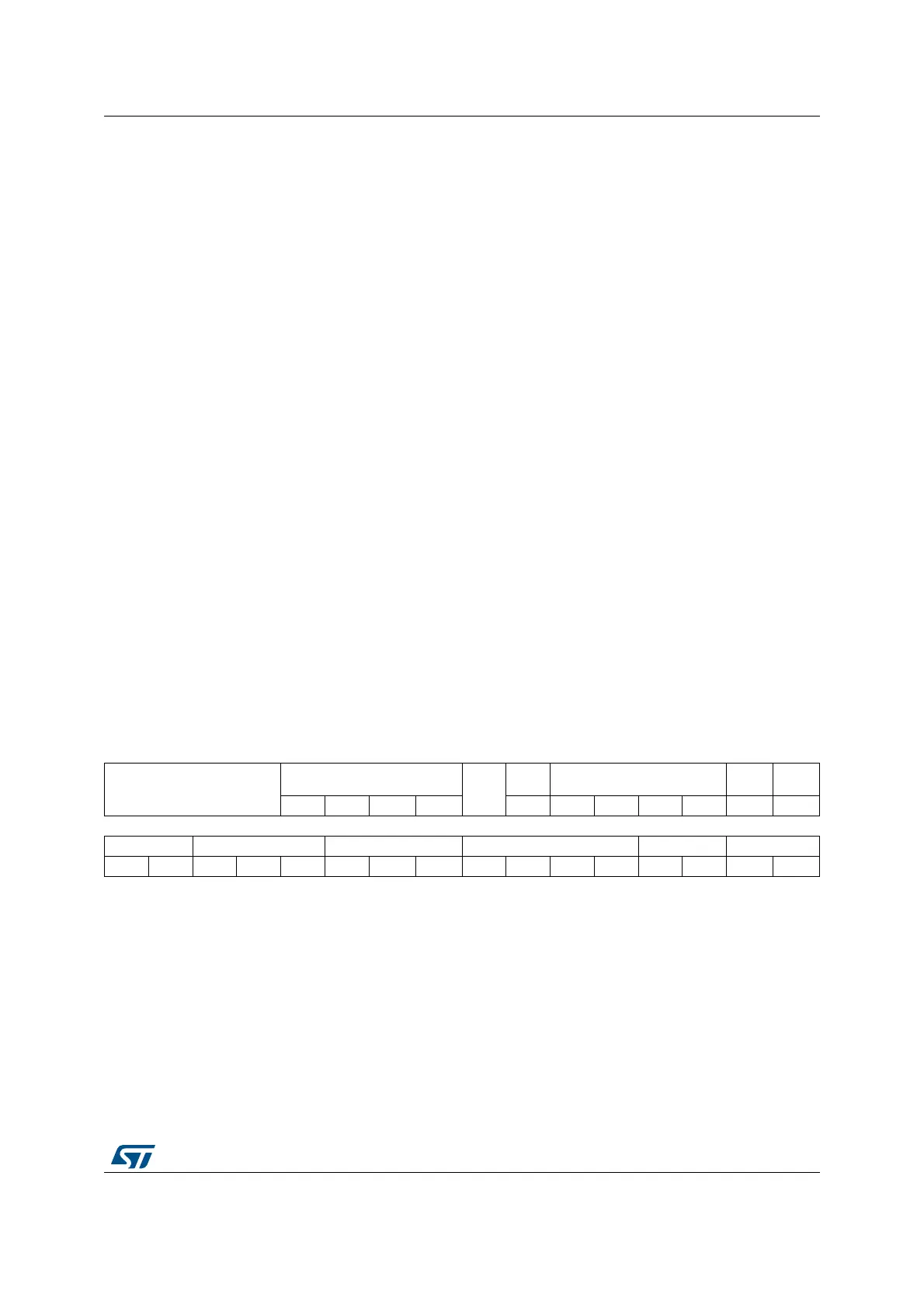
8.3.2 Clock configuration register (RCC_CFGR)
Address offset: 0x04
Reset value: 0x0000 0000
Access: 0 ≤ wait state ≤ 2, word, half-word and byte access
1 or 2 wait states inserted only if the access occurs during a clock source switch.
Bits 7:3 HSITRIM[4:0]: Internal high-speed clock trimming
These bits provide an additional user-programmable trimming value that is added to the
HSICAL[7:0] bits. It can be programmed to adjust to variations in voltage and temperature
that influence the frequency of the internal HSI RC.
The default value is 16, which, when added to the HSICAL value, should trim the HSI to 8
MHz ± 1%. The trimming step (F
hsitrim
) is around 40 kHz between two consecutive HSICAL
steps.
Bit 2 Reserved, must be kept at reset value.
Bit 1 HSIRDY: Internal high-speed clock ready flag
Set by hardware to indicate that internal 8 MHz RC oscillator is stable. After the HSION bit
is cleared, HSIRDY goes low after 6 internal 8 MHz RC oscillator clock cycles.
0: Internal 8 MHz RC oscillator not ready
1: Internal 8 MHz RC oscillator ready
Bit 0 HSION: Internal high-speed clock enable
Set and cleared by software.
Set by hardware to force the internal 8 MHz RC oscillator ON when leaving Stop or Standby
mode or in case of failure of the external 3-25 MHz oscillator used directly or indirectly as
system clock. This bit can not be cleared if the internal 8 MHz RC is used directly or
indirectly as system clock or is selected to become the system clock.
0: Internal 8 MHz RC oscillator OFF
1: Internal 8 MHz RC oscillator ON
31 30 29 28 27 26 25 24 23 22 21 20 19 18 17 16
Reserved
MCO[3:0]
Res.
OTGFS
PRE
PLLMUL[3:0]
PLL
XTPRE
PLL
SRC
rw rw rw rw rw rw rw rw rw rw rw
15 14 13 12 11 10 9 8 7 6 5 4 3 2 1 0
ADC PRE[1:0] PPRE2[2:0] PPRE1[2:0] HPRE[3:0] SWS[1:0] SW[1:0]
rw rw rw rw rw rw rw rw rw rw rw rw r r rw rw
 Loading...


