DocID13902 Rev 15 770/1128
RM0008 Inter-integrated circuit (I
2
C) interface
777
26.6.5 I
2
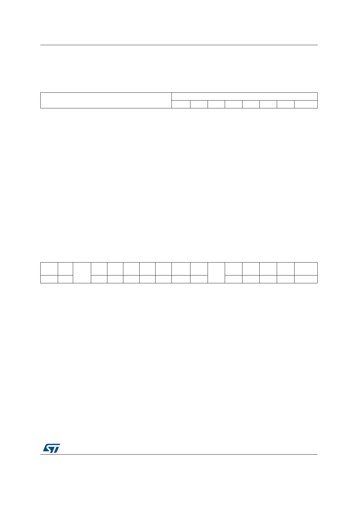
C Data register (I2C_DR)
Address offset: 0x10
Reset value: 0x0000
26.6.6 I
2
C Status register 1 (I2C_SR1)
Address offset: 0x14
Reset value: 0x0000
151413121110987 654321 0
Reserved
DR[7:0]
rw rw rw rw rw rw rw rw
Bits 15:8 Reserved, must be kept at reset value
Bits 7:0 DR[7:0] 8-bit data register
Byte received or to be transmitted to the bus.
– Transmitter mode: Byte transmission starts automatically when a byte is written in the DR
register. A continuous transmit stream can be maintained if the next data to be transmitted is
put in DR once the transmission is started (TxE=1)
– Receiver mode: Received byte is copied into DR (RxNE=1). A continuous transmit stream
can be maintained if DR is read before the next data byte is received (RxNE=1).
Note: In slave mode, the address is not copied into DR.
Write collision is not managed (DR can be written if TxE=0).
If an ARLO event occurs on ACK pulse, the received byte is not copied into DR
and so cannot be read.
151413121110987 654321 0
SMB
ALERT
TIME
OUT
Res.
PEC
ERR
OVR AF ARLO BERR TxE RxNE
Res.
STOPF ADD10 BTF ADDR SB
rc_w0rc_w0 rc_w0rc_w0rc_w0rc_w0rc_w0r r rrrr r
 Loading...


