USB on-the-go full-speed (OTG_FS) RM0008
825/1128 DocID13902 Rev 15
the physical support to USB connectivity.
The full-speed OTG PHY includes the following components:
• FS/LS transceiver module used by both host and device. It directly drives transmission
and reception on the single-ended USB lines.
• integrated ID pull-up resistor used to sample the ID line for A/B device identification.
• DP/DM integrated pull-up and pull-down resistors controlled by the OTG_FS core
depending on the current role of the device. As a peripheral, it enables the DP pull-up
resistor to signal full-speed peripheral connections as soon as V
BUS
is sensed to be at
a valid level (B-session valid). In host mode, pull-down resistors are enabled on both
DP/DM. Pull-up and pull-down resistors are dynamically switched when the device’s
role is changed via the host negotiation protocol (HNP).
• Pull-up/pull-down resistor ECN circuit. The DP pull-up consists of 2 resistors controlled
separately from the OTG_FS as per the resistor Engineering Change Notice applied to
USB Rev2.0. The dynamic trimming of the DP pull-up strength allows for better noise
rejection and Tx/Rx signal quality.
• V
BUS
sensing comparators with hysteresis used to detect V
BUS
Valid, A-B Session
Valid and session-end voltage thresholds. They are used to drive the session request
protocol (SRP), detect valid startup and end-of-session conditions, and constantly
monitor the V
BUS
supply during USB operations.
• V
BUS
pulsing method circuit used to charge/discharge V
BUS
through resistors during
the SRP (weak drive).
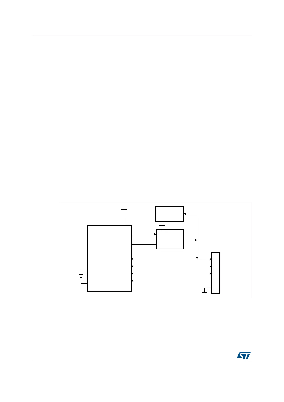
28.4 OTG dual role device (DRD)
Figure 303. OTG A-B device connection
1. External voltage regulator only needed when building a V
BUS
powered device
2. STMPS2141STR needed only if the application has to support a V
BUS
powered device. A basic power
switch can be used if 5 V are available on the application board.
34-&XX
34-&XX
34-03342
#URRENTLIMITED
POWERDISTRIBUTION
SWITCH
6
$$
6"53
$0
6
33
0!
0!
0!
53"
MICRO!"
CONNECTOR
$-
'0)/)21
'0)/
%.
/VERCURRENT
60WR
6TO6
$$
VOLTAGEREGULATOR
6
$$
)$
0!
/3#?).
/3#?/54
AIC
 Loading...


