General-purpose and alternate-function I/Os (GPIOs and AFIOs) RM0008
169/1128 DocID13902 Rev 15
The GPIO configuration of the ADC inputs should be analog.
OTG_FS_ID
Host
No need if the Force host mode is selected by software
(FHMOD set in the OTG_FS_GUSBCFG register)
Device
No need if the Force device mode is selected by software
(FDMOD set in the OTG_FS_GUSBCFG register)
OTG Input pull-up
OTG_FS_DM
Host Controlled automatically by the USB power-down
Device Controlled automatically by the USB power-down
OTG Controlled automatically by the USB power-down
OTG_FS_DP
Host Controlled automatically by the USB power-down
Device Controlled automatically by the USB power-down
OTG Controlled automatically by the USB power-down
1. This table applies to connectivity line devices only.
2. For the OTG_FS_VBUS pin (PA9) to be used by another shared peripheral or as a general-purpose IO, the
PHY Power-down mode has to be active (clear bit 16 in the OTG_FS_GCCFG register).
Table 31. SDIO
SDIO pinout GPIO configuration
SDIO_CK Alternate function push-pull
SDIO_CMD Alternate function push-pull
SDIO[D7:D0] Alternate function push-pull
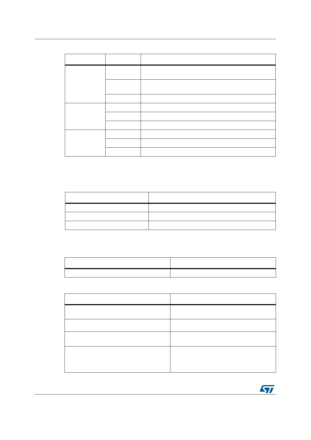
Figure 19. ADC / DAC
ADC/DAC pin GPIO configuration
ADC/DAC Analog
Table 32. FSMC
FSMC pinout GPIO configuration
FSMC_A[25:0]
FSMC_D[15:0]
Alternate function push-pull
FSMC_CK Alternate function push-pull
FSMC_NOE
FSMC_NWE
Alternate function push-pull
FSMC_NE[4:1]
FSMC_NCE[3:2]
FSMC_NCE4_1
FSMC_NCE4_2
Alternate function push-pull
Table 30. OTG_FS pin configuration
(1)
OTG_FS pinout Configuration GPIO configuration
 Loading...


