Inter-integrated circuit (I
2
C) interface RM0008
745/1128 DocID13902 Rev 15
26.3 I
2
C functional description
In addition to receiving and transmitting data, this interface converts it from serial to parallel
format and vice versa. The interrupts are enabled or disabled by software. The interface is
connected to the I
2
C bus by a data pin (SDA) and by a clock pin (SCL). It can be connected
with a standard (up to 100 kHz) or fast (up to 400 kHz) I
2
C bus.
26.3.1 Mode selection
The interface can operate in one of the four following modes:
• Slave transmitter
• Slave receiver
• Master transmitter
• Master receiver
By default, it operates in slave mode. The interface automatically switches from slave to
master, after it generates a START condition and from master to slave, if an arbitration loss
or a Stop generation occurs, allowing multimaster capability.
Communication flow
In Master mode, the I
2
C interface initiates a data transfer and generates the clock signal. A
serial data transfer always begins with a start condition and ends with a stop condition. Both
start and stop conditions are generated in master mode by software.
In Slave mode, the interface is capable of recognizing its own addresses (7 or 10-bit), and
the General Call address. The General Call address detection may be enabled or disabled
by software.
Data and addresses are transferred as 8-bit bytes, MSB first. The first byte(s) following the
start condition contain the address (one in 7-bit mode, two in 10-bit mode). The address is
always transmitted in Master mode.
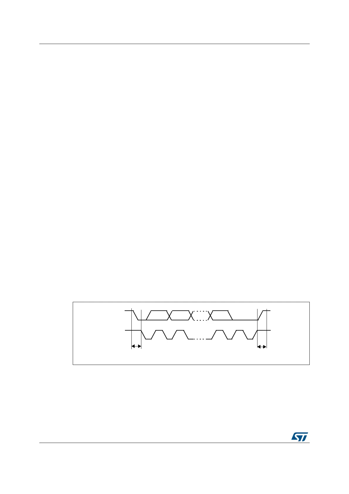
A 9th clock pulse follows the 8 clock cycles of a byte transfer, during which the receiver must
send an acknowledge bit to the transmitter. Refer to Figure 268.
Figure 268. I
2
C bus protocol
Acknowledge may be enabled or disabled by software. The I
2
C interface addresses (dual
addressing 7-bit/ 10-bit and/or general call address) can be selected by software.
The block diagram of the I
2
C interface is shown in Figure 269.
SCL
SDA
12 8 9
MSB
ACK
Stop
Start
condition
condition
 Loading...


