Inter-integrated circuit (I
2
C) interface RM0008
767/1128 DocID13902 Rev 15
Note: When the STOP, START or PEC bit is set, the software must not perform any write access
to I2C_CR1 before this bit is cleared by hardware. Otherwise there is a risk of setting a
second STOP, START or PEC request.
26.6.2 I
2
C Control register 2 (I2C_CR2)
Address offset: 0x04
Reset value: 0x0000
Bit 3 SMBTYPE: SMBus type
0: SMBus Device
1: SMBus Host
Bit 2 Reserved, must be kept at reset value
Bit 1 SMBUS: SMBus mode
0: I
2
C mode
1: SMBus mode
Bit 0 PE: Peripheral enable
0: Peripheral disable
1: Peripheral enable
Note: If this bit is reset while a communication is on going, the peripheral is disabled at the
end of the current communication, when back to IDLE state.
All bit resets due to PE=0 occur at the end of the communication.
In master mode, this bit must not be reset before the end of the communication.
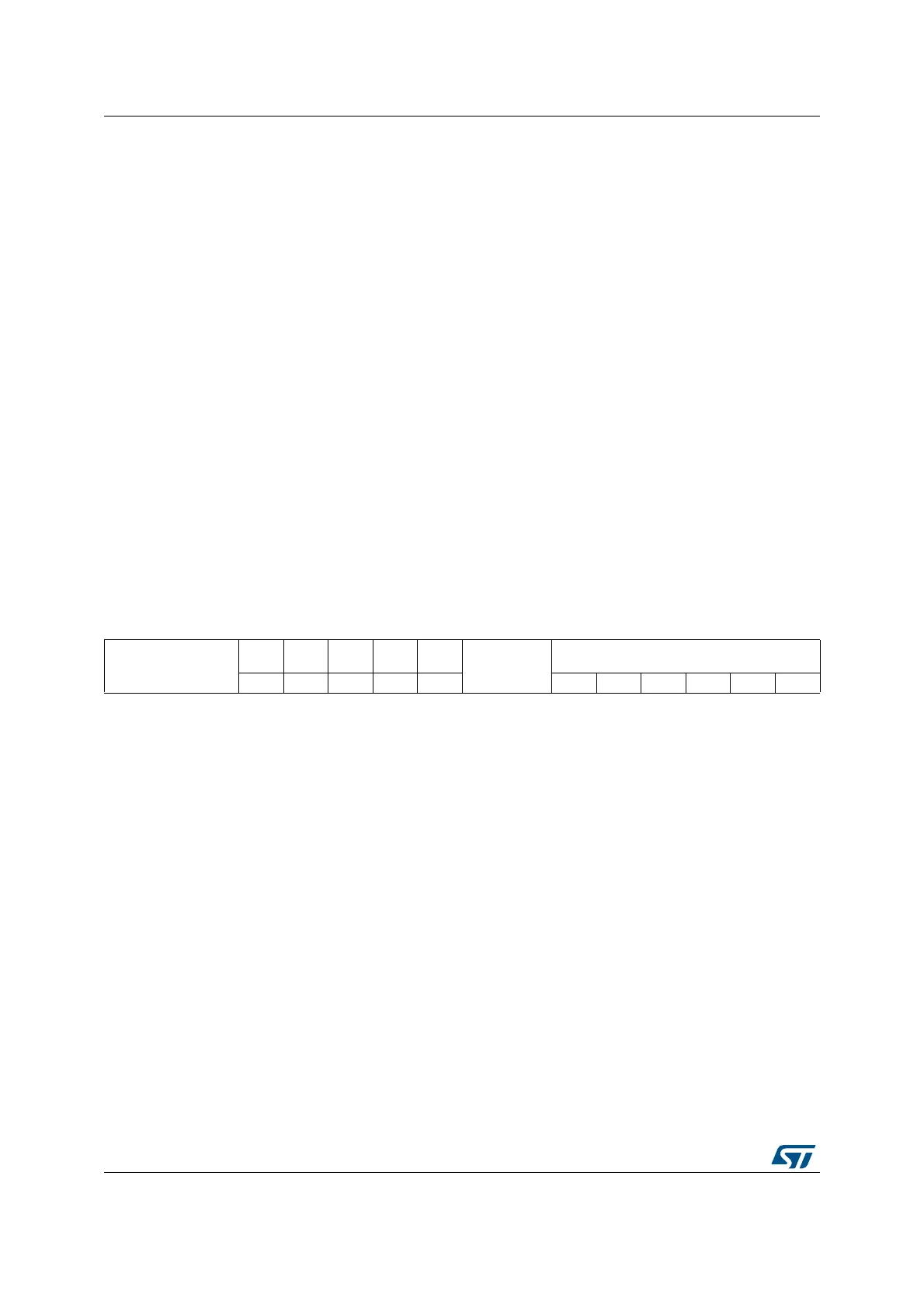
1514131211109876543210
Reserved
LAST
DMA
EN
ITBUF
EN
ITEVTE
N
ITERR
EN
Reserved
FREQ[5:0]
rw rw rw rw rw rw rw rw rw rw rw
Bits 15:13 Reserved, must be kept at reset value
Bit 12 LAST: DMA last transfer
0: Next DMA EOT is not the last transfer
1: Next DMA EOT is the last transfer
Note: This bit is used in master receiver mode to permit the generation of a NACK on the last
received data.
Bit 11 DMAEN: DMA requests enable
0: DMA requests disabled
1: DMA request enabled when TxE=1 or RxNE =1
Bit 10 ITBUFEN: Buffer interrupt enable
0: TxE = 1 or RxNE = 1 does not generate any interrupt.
1: TxE = 1 or RxNE = 1 generates Event Interrupt (whatever the state of DMAEN)
 Loading...


