Analog-to-digital converter (ADC) RM0008
237/1128 DocID13902 Rev 15
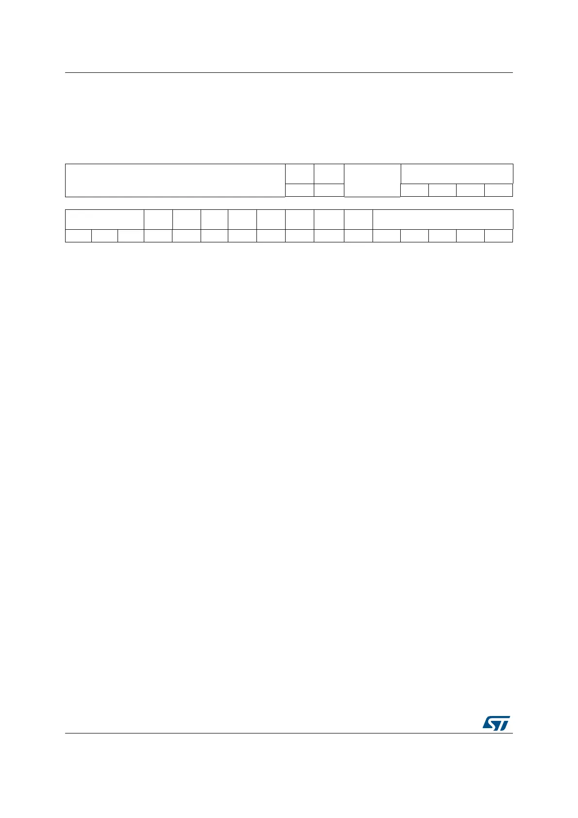
11.12.2 ADC control register 1 (ADC_CR1)
Address offset: 0x04
Reset value: 0x0000 0000
31 30 29 28 27 26 25 24 23 22 21 20 19 18 17 16
Reserved
AWDE
N
JAWDE
N
Reserved
DUALMOD[3:0]
rw rw rw rw rw rw
15 14 13 12 11 10 9 8 7 6 5 4 3 2 1 0
DISCNUM[2:0]
JDISCE
N
DISC
EN
JAUTO
AWD
SGL
SCAN
JEOC
IE
AWDIE EOCIE AWDCH[4:0]
rw rw rw rw rw rw rw rw rw rw rw rw rw rw rw rw
Bits 31:24 Reserved, must be kept at reset value.
Bit 23 AWDEN: Analog watchdog enable on regular channels
This bit is set/reset by software.
0: Analog watchdog disabled on regular channels
1: Analog watchdog enabled on regular channels
Bit 22 JAWDEN: Analog watchdog enable on injected channels
This bit is set/reset by software.
0: Analog watchdog disabled on injected channels
1: Analog watchdog enabled on injected channels
Bits 21:20 Reserved, must be kept at reset value.
Bits 19:16 DUALMOD[3:0]: Dual mode selection
These bits are written by software to select the operating mode.
0000: Independent mode.
0001: Combined regular simultaneous + injected simultaneous mode
0010: Combined regular simultaneous + alternate trigger mode
0011: Combined injected simultaneous + fast interleaved mode
0100: Combined injected simultaneous + slow Interleaved mode
0101: Injected simultaneous mode only
0110: Regular simultaneous mode only
0111: Fast interleaved mode only
1000: Slow interleaved mode only
1001: Alternate trigger mode only
Note: These bits are reserved in ADC2 and ADC3.
In dual mode, a change of channel configuration generates a restart that can produce a
loss of synchronization. It is recommended to disable dual mode before any
configuration change.
Bits 15:13 DISCNUM[2:0]: Discontinuous mode channel count
These bits are written by software to define the number of regular channels to be converted
in discontinuous mode, after receiving an external trigger.
000: 1 channel
001: 2 channels
.......
111: 8 channels
 Loading...


