DocID13902 Rev 15 844/1128
RM0008 USB on-the-go full-speed (OTG_FS)
957
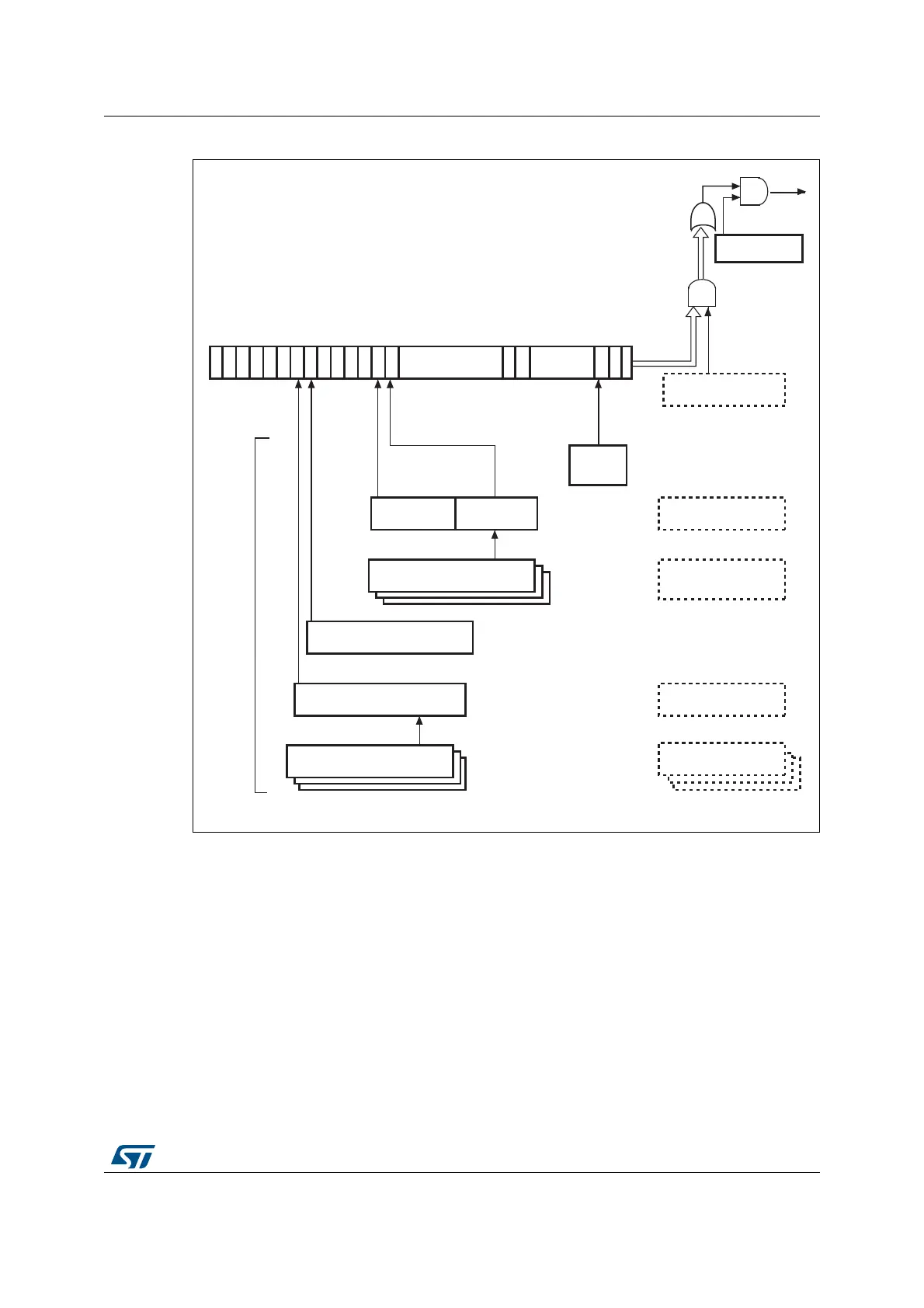
Figure 310. Interrupt hierarchy
1. The core interrupt register bits are shown in OTG_FS core interrupt register (OTG_FS_GINTSTS) on
page 859.
28.16 OTG_FS control and status registers
By reading from and writing to the control and status registers (CSRs) through the AHB
slave interface, the application controls the OTG_FS controller. These registers are 32 bits
wide, and the addresses are 32-bit block aligned. The OTG_FS registers must be accessed
by words (32 bits).
31 30 29 28 27 26 25 24 23 20 19 18 17:10 9 8 7:3 2 1 0
AND
OR
Interrupt
Global interrupt
mask (Bit 0)
AHB configuration
register
Core interrupt mask
register
OTG
interrupt
register
Core interrupt
register
(1)
Device IN/OUT endpoint
interrupt registers 0 to 3
Device all endpoints
interrupt register
16:9
OUT endpoints
3:0
IN endpoints
Interrupt
sources
Host port control and status
register
Host all channels interrupt
register
Host channels interrupt
mask registers 0 to 7
Host all channels
interrupt mask register
Host channels interrupt
registers 0 to 7
22 21
Device all endpoints
interrupt mask register
Device IN/OUT
endpoints common
interrupt mask register
ai15616b
 Loading...


