Analog-to-digital converter (ADC) RM0008
249/1128 DocID13902 Rev 15
11.12.12 ADC injected sequence register (ADC_JSQR)
Address offset: 0x38
Reset value: 0x0000 0000
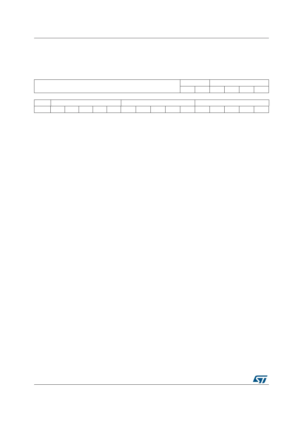
31 30 29 28 27 26 25 24 23 22 21 20 19 18 17 16
Reserved
JL[1:0] JSQ4[4:1]
rw rw rw rw rw rw
15 14 13 12 11 10 9 8 7 6 5 4 3 2 1 0
JSQ4_0 JSQ3[4:0] JSQ2[4:0] JSQ1[4:0]
rw rw rw rw rw rw rw rw rw rw rw rw rw rw rw rw
Bits 31:22 Reserved, must be kept at reset value.
Bits 21:20 JL[1:0]: Injected sequence length
These bits are written by software to define the total number of conversions in the injected
channel conversion sequence.
00: 1 conversion
01: 2 conversions
10: 3 conversions
11: 4 conversions
Bits 19:15 JSQ4[4:0]: 4th conversion in injected sequence (when JL[1:0] = 3)
(1)
These bits are written by software with the channel number (0..17) assigned as the 4th in
the sequence to be converted.
Note: Unlike a regular conversion sequence, if JL[1:0] length is less than four, the channels
are converted in a sequence starting from (4-JL). Example: ADC_JSQR[21:0] = 10
00011 00011 00111 00010 means that a scan conversion will convert the following
channel sequence: 7, 3, 3. (not 2, 7, 3)
Bits 14:10 JSQ3[4:0]: 3rd conversion in injected sequence (when JL[1:0] = 3)
Bits 9:5 JSQ2[4:0]: 2nd conversion in injected sequence (when JL[1:0] = 3)
Bits 4:0 JSQ1[4:0]: 1st conversion in injected sequence (when JL[1:0] = 3)
1. When JL=3 ( 4 injected conversions in the sequencer), the ADC converts the channels in this order:
JSQ1[4:0] >> JSQ2[4:0] >> JSQ3[4:0] >> JSQ4[4:0]
When JL=2 ( 3 injected conversions in the sequencer), the ADC converts the channels in this order:
JSQ2[4:0] >> JSQ3[4:0] >> JSQ4[4:0]
When JL=1 ( 2 injected conversions in the sequencer), the ADC converts the channels in this order:
JSQ3[4:0] >> JSQ4[4:0]
When JL=0 (1 injected conversion in the sequencer), the ADC converts only JSQ4[4:0] channel
 Loading...


