Ethernet (ETH): media access control (MAC) with DMA controller RM0008
967/1128 DocID13902 Rev 15
deasserted and MII_RX_ER is asserted, a specific MII_RXD[3:0] value is used to
transfer specific information from the PHY (see Table 212).
• MII_RX_DV: receive data valid indicates that the PHY is presenting recovered and
decoded nibbles on the MII for reception. It must be asserted synchronously
(MII_RX_CLK) with the first recovered nibble of the frame and must remain asserted
through the final recovered nibble. It must be deasserted prior to the first clock cycle
that follows the final nibble. In order to receive the frame correctly, the MII_RX_DV
signal must encompass the frame, starting no later than the SFD field.
• MII_RX_ER: receive error must be asserted for one or more clock periods
(MII_RX_CLK) to indicate to the MAC sublayer that an error was detected somewhere
in the frame. This error condition must be qualified by MII_RX_DV assertion as
described in Table 212.
MII clock sources
To generate both TX_CLK and RX_CLK clock signals, the external PHY must be clocked
with an external 25 MHz as shown in Figure 331. Instead of using an external 25 MHz
quartz to provide this clock, the STM32F10xxx microcontroller can output this signal on its
MCO pin. In this case, the PLL multiplier has to be configured so as to get the desired
frequency on the MCO pin, from the 25 MHz external quartz.
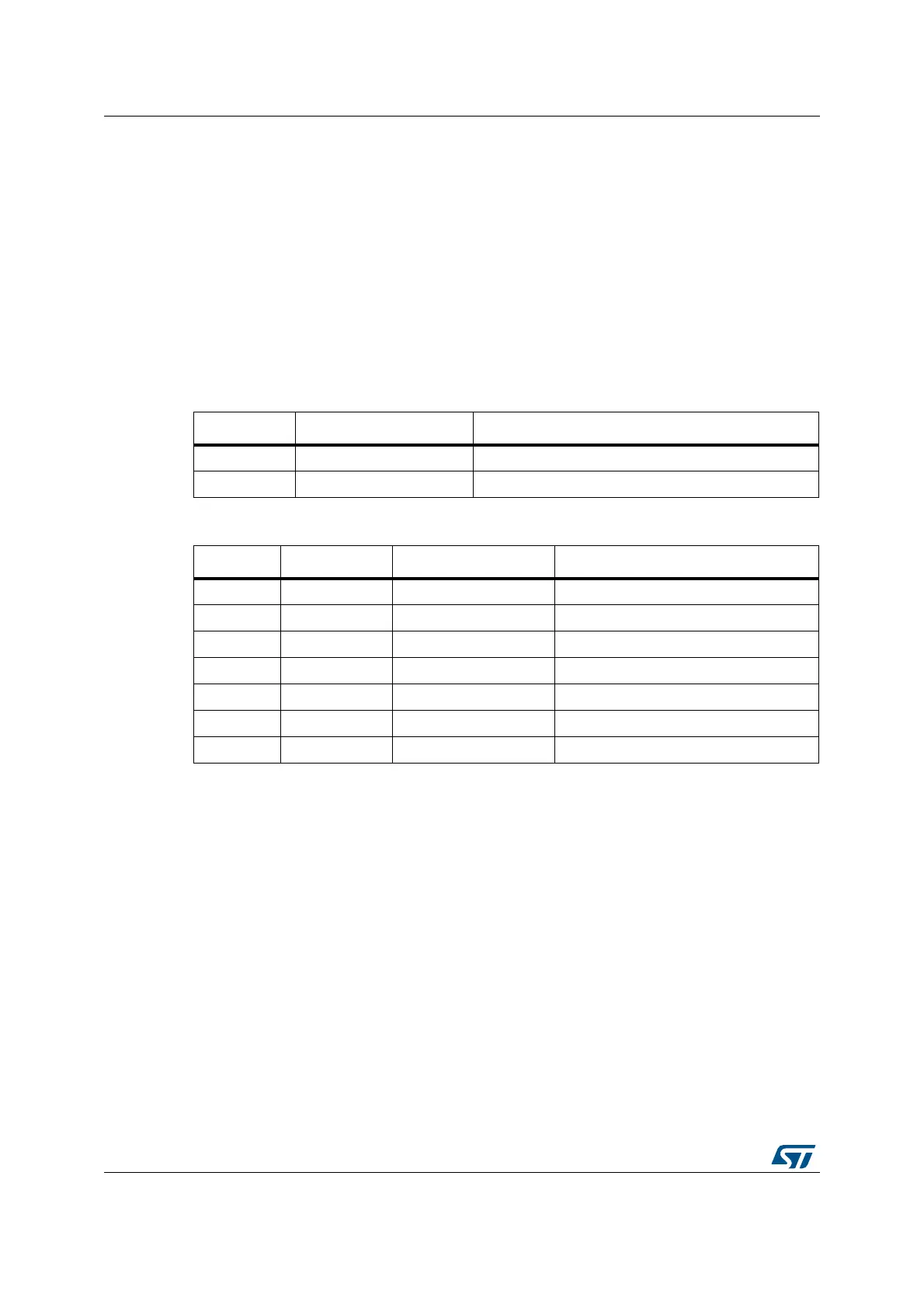
Table 211. TX interface signal encoding
MII_TX_EN MII_TXD[3:0] Description
0 0000 through 1111 Normal inter-frame
1 0000 through 1111 Normal data transmission
Table 212. RX interface signal encoding
MII_RX_DV MII_RX_ERR MII_RXD[3:0] Description
0 0 0000 through 1111 Normal inter-frame
0 1 0000 Normal inter-frame
0 1 0001 through 1101 Reserved
0 1 1110 False carrier indication
0 1 1111 Reserved
1 0 0000 through 1111 Normal data reception
1 1 0000 through 1111 Data reception with errors
 Loading...


