Ethernet (ETH): media access control (MAC) with DMA controller RM0008
963/1128 DocID13902 Rev 15
The application can select one of the 32 PHYs and one of the 32 registers within any PHY
and send control data or receive status information. Only one register in one PHY can be
addressed at any given time.
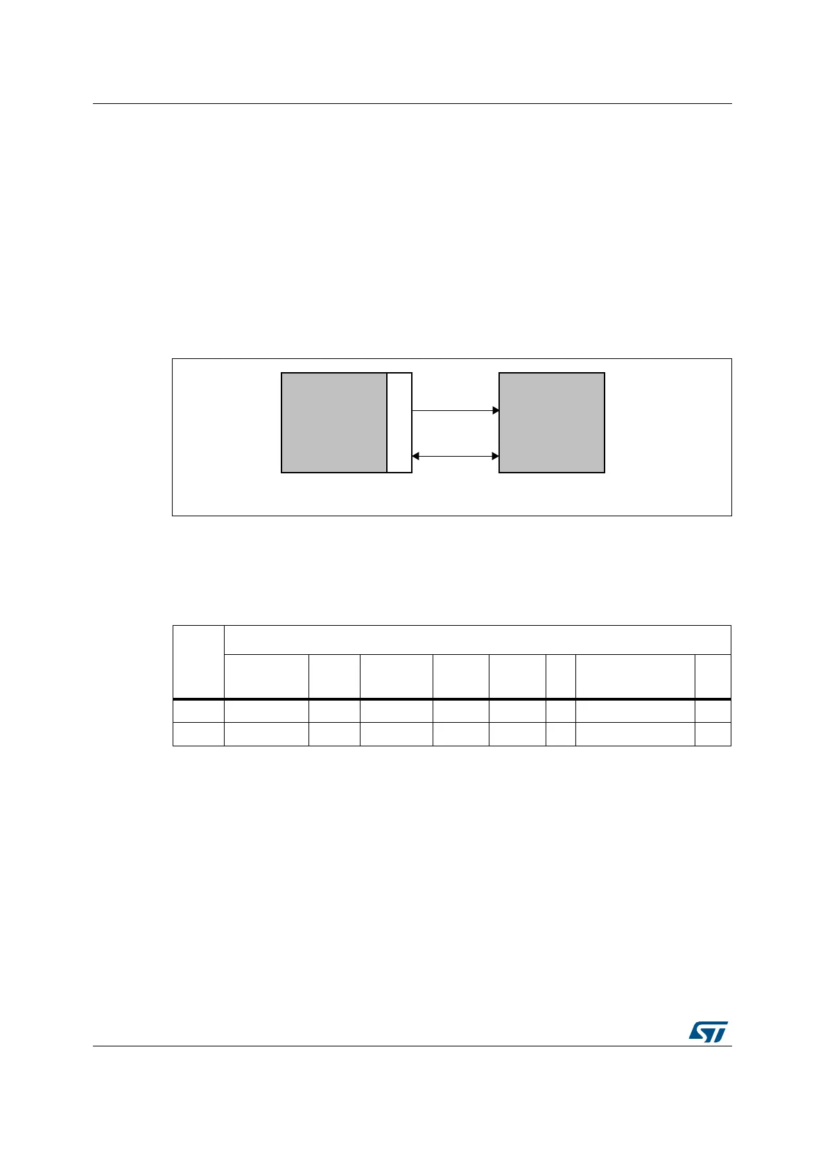
Both the MDC clock line and the MDIO data line are implemented as alternate function I/O
in the microcontroller:
• MDC: a periodic clock that provides the timing reference for the data transfer at the
maximum frequency of 2.5 MHz. The minimum high and low times for MDC must be
160 ns each, and the minimum period for MDC must be 400 ns. In idle state the SMI
management interface drives the MDC clock signal low.
• MDIO: data input/output bitstream to transfer status information to/from the PHY device
synchronously with the MDC clock signal
Figure 327. SMI interface signals
SMI frame format
The frame structure related to a read or write operation is shown in Table 13, the order of bit
transmission must be from left to right.
Table 209. Management frame format
Management frame fields
Preamble
(32 bits)
Start Operation PADDR RADDR TA Data (16 bits) Idle
Read 1... 1 01 10 ppppp rrrrr Z0 ddddddddddddddd Z
Write 1... 1 01 01 ppppp rrrrr 10 ddddddddddddddd Z
6700&8
0',2
0'&
([WHUQDO
3+<
DLE
-!#
 Loading...


