Universal synchronous asynchronous receiver transmitter (USART) RM0008
807/1128 DocID13902 Rev 15
Reception using DMA
DMA mode can be enabled for reception by setting the DMAR bit in USART_CR3 register.
Data is loaded from the USART_DR register to a SRAM area configured using the DMA
peripheral (refer to the DMA specification) whenever a data byte is received. To map a DMA
channel for USART reception, use the following procedure:
1. Write the USART_DR register address in the DMA control register to configure it as the
source of the transfer. The data will be moved from this address to the memory after
each RXNE event.
2. Write the memory address in the DMA control register to configure it as the destination
of the transfer. The data will be loaded from USART_DR to this memory area after each
RXNE event.
3. Configure the total number of bytes to be transferred in the DMA control register.
4. Configure the channel priority in the DMA control register
5. Configure interrupt generation after half/ full transfer as required by the application.
6. Activate the channel in the DMA control register.
When the number of data transfers programmed in the DMA Controller is reached, the DMA
controller generates an interrupt on the DMA channel interrupt vector.
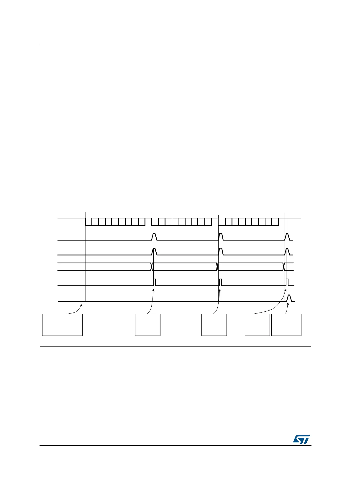
Figure 297. Reception using DMA
Error flagging and interrupt generation in multibuffer communication
In case of multibuffer communication if any error occurs during the transaction the error flag
will be asserted after the current byte. An interrupt will be generated if the interrupt enable
flag is set. For framing error, overrun error and noise flag which are asserted with RXNE in
case of single byte reception, there will be separate error flag interrupt enable bit (EIE bit in
the USART_CR3 register), which if set will issue an interrupt after the current byte with
either of these errors.
TX line
USART_DR
Frame 1
RXNE flag
F2 F3
Frame 2
Frame 3
set by hardware
cleared by DMA read
F1
software configures the
DMA to receive 3 data
blocks and enables
the USART
DMA request
DMA reads SPI_DR
DMA TCIF flag
set by hardware
cleared
by software
DMA reads F1
from
USART_DR
(Transfer complete)
DMA reads F2
from
USART_DR
DMA reads F3
from
USART_DR
The DMA transfer
is complete
(TCIF=1 in
DMA_ISR)
ai17193
 Loading...


