Universal synchronous asynchronous receiver transmitter (USART) RM0008
801/1128 DocID13902 Rev 15
Apart from this, the communications are similar to what is done in normal USART mode.
The conflicts on the line must be managed by the software (by the use of a centralized
arbiter, for instance). In particular, the transmission is never blocked by hardware and
continue to occur as soon as a data is written in the data register while the TE bit is set.
27.3.11 Smartcard
The Smartcard mode is selected by setting the SCEN bit in the USART_CR3 register. In
smartcard mode, the following bits must be kept cleared:
• LINEN bit in the USART_CR2 register,
• HDSEL and IREN bits in the USART_CR3 register.
Moreover, the CLKEN bit may be set in order to provide a clock to the smartcard.
The Smartcard interface is designed to support asynchronous protocol Smartcards as
defined in the ISO 7816-3 standard. The USART should be configured as:
• 8 bits plus parity: where M=1 and PCE=1 in the USART_CR1 register
• 1.5 stop bits when transmitting and receiving : where STOP=’11’ in the USART_CR2
register.
Note: It is also possible to choose 0.5 stop bit for receiving but it is recommended to use 1.5 stop
bits for both transmitting and receiving to avoid switching between the two configurations.
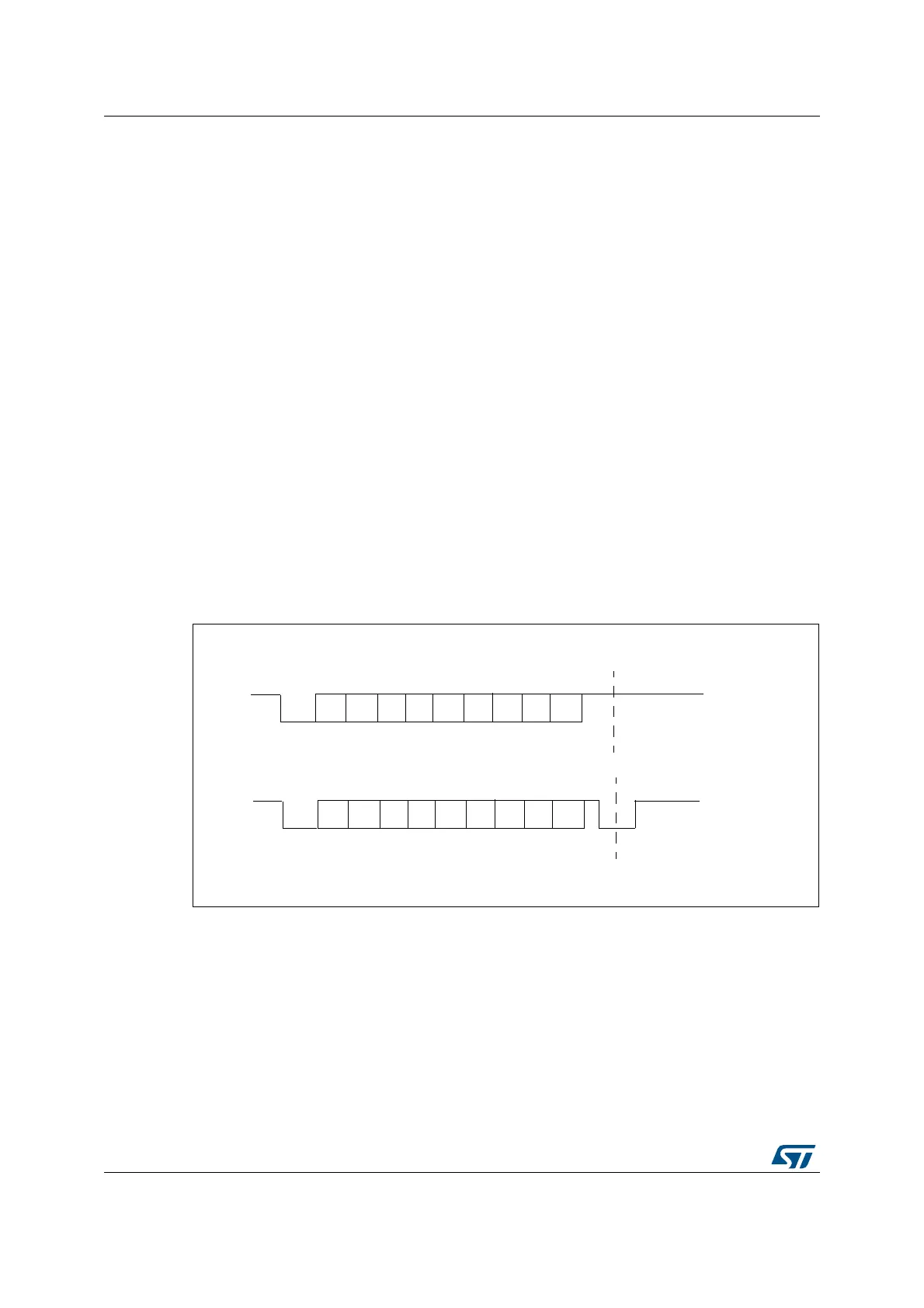
Figure 292 shows examples of what can be seen on the data line with and without parity
error.
Figure 292. ISO 7816-3 asynchronous protocol
When connected to a smartcard, the USART TX output drives a bidirectional line that is also
driven by the smartcard. The TX pin must be configured as open drain.
S
0
1
23
5
4
67
P
Start
bit
Guard time
S
0
1
23
5
4
67
P
Start
bit
Line pulled low
by receiver during stop in
case of parity error
Guard time
Without Parity error
With Parity error
 Loading...


