Engine General Information and Diagnosis: 1A-30
DTC “C13” (P1750) or “C17” (P0105): IAP Sensor Circuit Malfunction
B944H11104011
Detected Condition and Possible Cause
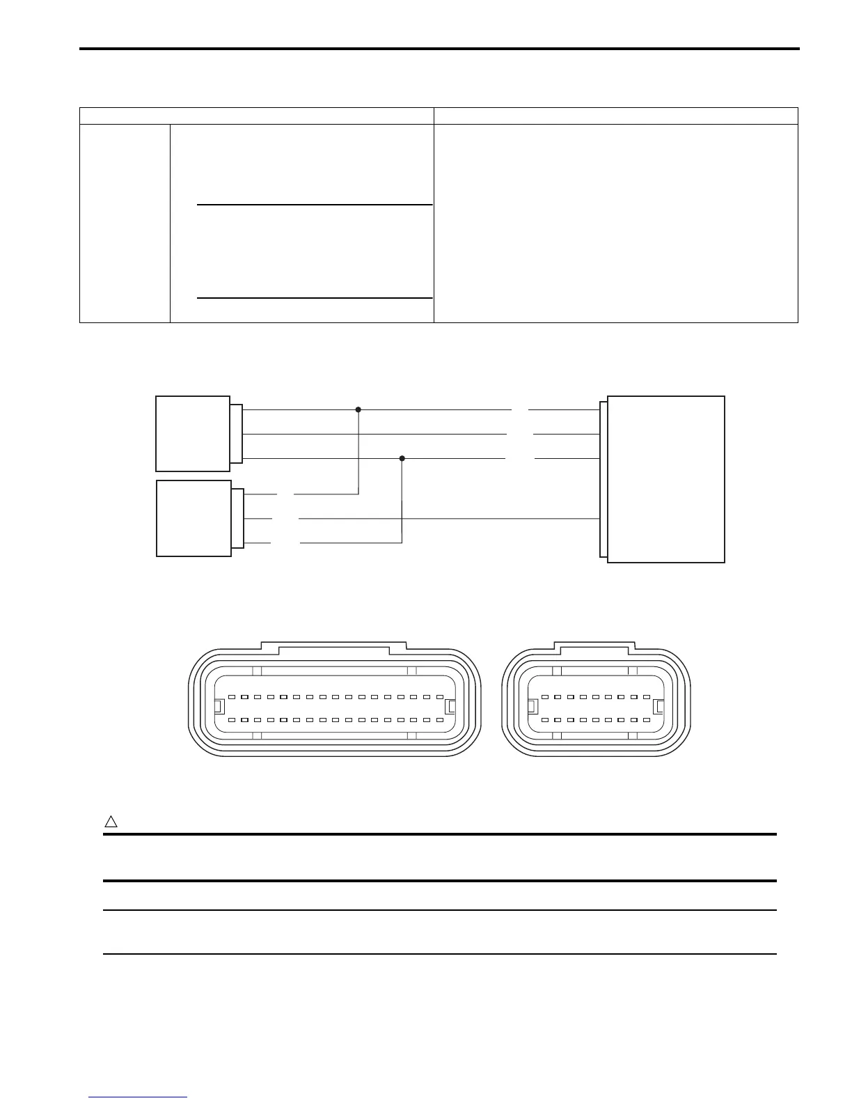
Wiring Diagram
ECM coupler (Harness side)
Troubleshooting
CAUTION
!
When using the multi-circuit tester, do not strongly touch the terminal of the ECM coupler with a
needle pointed tester probe to prevent terminal damage.
NOTE
After repairing the trouble, clear the DTC using SDS tool. Refer to “Use of SDS Diagnosis Reset
Procedures (Page 1A-15)”.
Detected Condition Possible Cause
C13/C17
IAP sensor voltage is not within the
following range.
0.1 V ≤ Sensor voltage < 4.8 V
NOTE
Note that atmospheric pressure
varies depending on weather
conditions as well as altitude.
Take that into consideration
when inspecting voltage.
• Clogged vacuum passage between throttle body and
IAP sensor.
• Air being drawn from vacuum passage between throttle
body and IAP sensor.
• IAP sensor circuit open or shorted to ground.
• IAP sensor malfunction.
• ECM malfunction.
ECM
R
G/B
B/Br
VCC
IAP. #1
E2
IAP sensor (#1)
IAP sensor (#2)
R
G/Y
B/Br
IAP. #2
3
5
22
12
I944H1110013-04
1234567891011121314151617
18
18 19 20 21 22 23 26 2724 25 28 29 30 31 32 33 34
35
36
37 38 39 40 41 42 43
44 45 46 47 48 49 50 51 52
I944H1110014-01

 Loading...


