Wheels and Tires: 2D-15
Tire Removal and Installation
B944H12406011
Removal
The most critical factor of a tubeless tire is the seal
between the wheel rim and the tire bead. For this
reason, it is recommended to use a tire changer that can
satisfy this sealing requirement and can make the
operation efficient as well as functional.
1) Removal the wheel assembly. Refer to “Front Wheel
Assembly Removal and Installation (Page 2D-4)”
and “Rear Wheel Assembly Removal and Installation
(Page 2D-11)”.
2) Remove the mounting drum from the rear wheel.
Refer to “Rear Wheel Dust Seal / Bearing Removal
and Installation (Page 2D-13)”.
3) Remove the valve core.
4) Remove the tire using the tire changer.
CAUTION
!
For operating procedures, refer to the
instructions supplied by the tire changer
manufacturer.
NOTE
When removing the tire in case of repair or
inspection, mark the tire with a chalk to
indicate the tire position relative to the valve
position. Even though the tire is refitted to
the original position after repairing puncture,
the tire may have to be balanced again since
such a repair can cause imbalance.
Installation
CAUTION
!
Do not reuse the valve which has been once
removed.
1) Apply tire lubricant to the tire bead.
CAUTION
!
Never use oil, grease or gasoline on the tire
bead in place of tire lubricant.
2) Install the tire onto the wheel.
CAUTION
!
For installation procedure of tire onto the
wheel, follow the instructions given by the
tire changer manufacturer.
NOTE
• When installing the tire, the arrow “A” on
the side wall should point to the direction
of wheel rotation.
• Align the chalk mark put on the tire at the
time of removal with the valve position.
3) Bounce the tire several times while rotating. This
makes the tire bead expand outward to contact the
wheel, thereby facilitating air inflation.
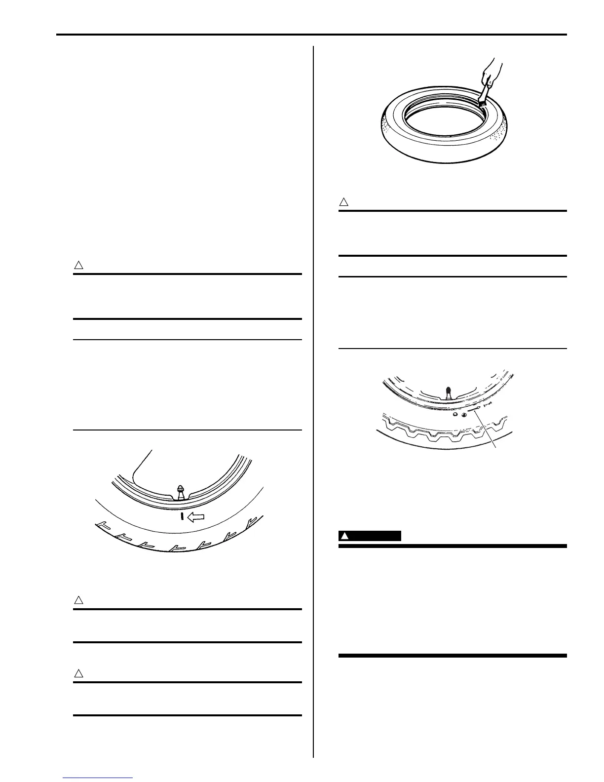
4) Install the valve core and inflate the tire.
WARNING
!
• Do not inflate the tire to more than 400 kPa
(4.0 kgf/cm
2
). If inflated beyond this limit,
the tire can burst and possibly cause
injury. Do not stand directly over the tire
while inflating.
• In the case of preset pressure air inflator,
pay special care for the set pressure
adjustment.
5) In this condition, check the “rim line” “B” cast on the
tire side walls. The line must be equidistant from the
wheel rim all around.
I649G1240037-02
I649G1240038-02
“A”
I649G1240039-02

 Loading...


