TMS320C6455
www.ti.com
SPRS276M –MAY 2005–REVISED MARCH 2012
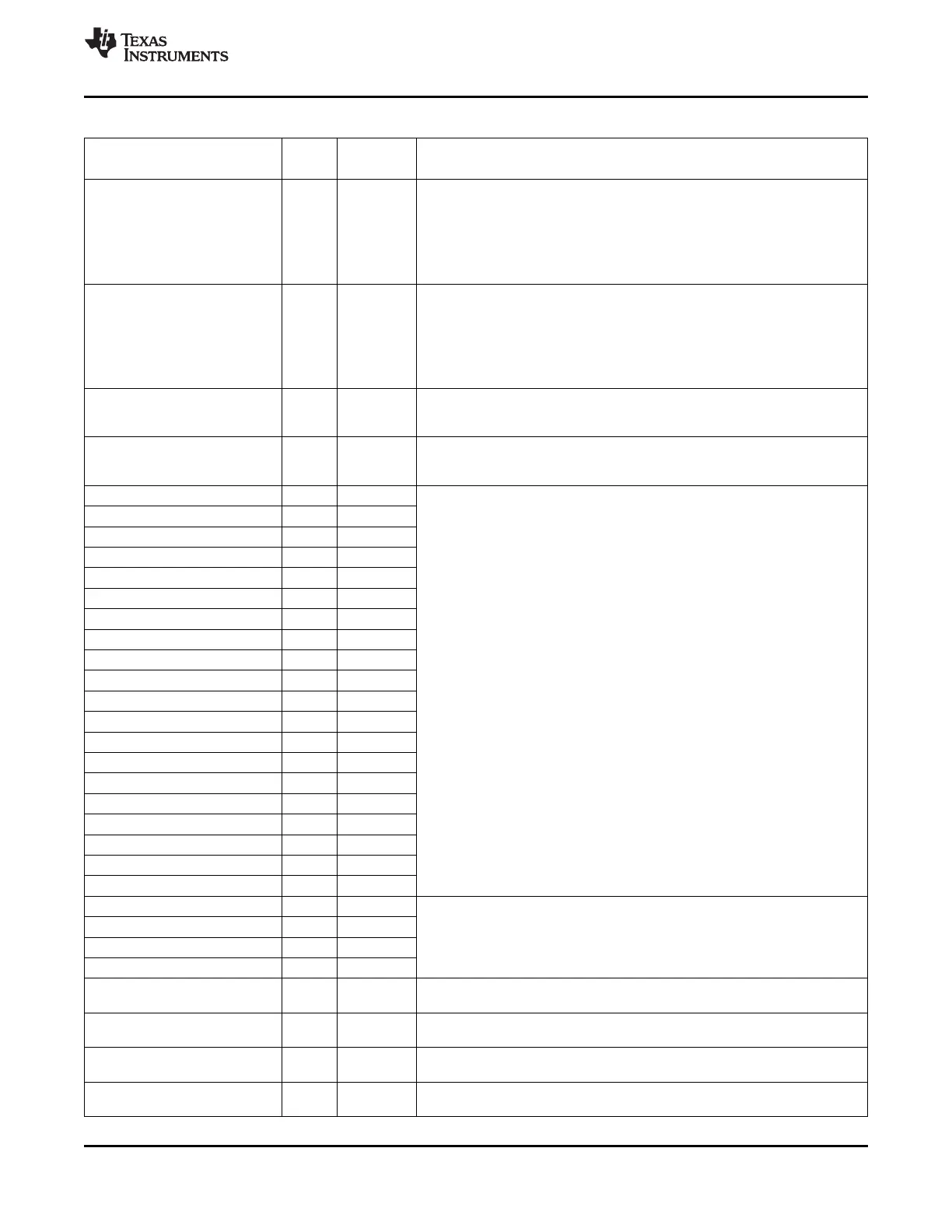
Table 2-3. Terminal Functions (continued)
SIGNAL
TYPE
(1)
IPD/IPU
(2)
DESCRIPTION
NAME NO.
Reserved. This pin must be connected to ground (V
SS
) via a 200-Ω resistor for
proper device operation.
NOTE: If the RGMII mode of the EMAC is not used, the DV
DD15
, V
REFHSTL
,
RSV13 F2 RSV13, and RSV14 pins can be connected to directly ground (V
SS
) to save
power. However, connecting these pins directly to ground will prevent
boundary-scan from functioning on the RGMII pins of the EMAC. To preserve
boundary-scan functionality on the RGMII pins, see Section 7.3.4.
Reserved. This pin must be connected to the 1.5/1.8-V I/O supply (DV
DD15
) via
a 200-Ω resistor for proper device operation.
NOTE: If the RGMII mode of the EMAC is not used, the DV
DD15
, V
REFHSTL
,
RSV14 F1 RSV13, and RSV14 pins can be connected to directly ground (V
SS
) to save
power. However, connecting these pins directly to ground will prevent
boundary-scan from functioning on the RGMII pins of the EMAC. To preserve
boundary-scan functionality on the RGMII pins, see Section 7.3.4.
Reserved. This pin must be connected via a 39-Ω resistor directly to ground
RSV15 T1 (V
SS
) for proper device operation. The resistor used should have a minimal
rating of 1/10 W.
Reserved. This pin must be connected via a 20-Ω resistor directly to 3.3-V I/O
RSV16 T2 Supply (DV
DD33
) for proper device operation. The resistor used should have a
minimal rating of 1/10 W.
RSV17 AE21 A
RSV18 E13 A
RSV19 F18 A
RSV20 U29 A
RSV21 A6 A
RSV22 B26 O
RSV23 C26 O
RSV24 B6 O
RSV25 C6 O
RSV26 AJ11 A
Reserved. (Leave unconnected, do not connect to power or ground.)
RSV27 AH11 A
RSV36 AD11 I/O/Z IPU
RSV37 AD9 I/O/Z IPU
RSV38 AG10 I/O/Z IPU
RSV39 AG11 I/O/Z IPU
RSV40 AJ12 I/O/Z IPU
RSV41 W28 O/Z IPU
RSV42 Y26 O/Z IPU
RSV43 Y25 O/Z IPU
RSV44 Y27 O/Z
RSV28 N7 A
RSV29 N6 A
Reserved. These pins must be connected directly to V
SS
for proper device
operation.
RSV30 P23 A
RSV31 P24 A
Reserved. This pin must be connected to the 1.8-V I/O supply (DV
DD18
) via a 1-
RSV32 D25
kΩ resistor for proper device operation.
Reserved. This pin must be connected directly to ground for proper device
RSV33 C25
operation.
Reserved. This pin must be connected to the 1.8-V I/O supply (DV
DD18
) via a 1-
RSV34 E6
kΩ resistor for proper device operation.
Reserved. This pin must be connected directly to ground for proper device
RSV35 D6
operation.
Copyright © 2005–2012, Texas Instruments Incorporated Device Overview 41
Submit Documentation Feedback
Product Folder Link(s): TMS320C6455