Fuses (continued)
Front Fuse Panel Layout (Serial # 01001 — 02172) (continued)
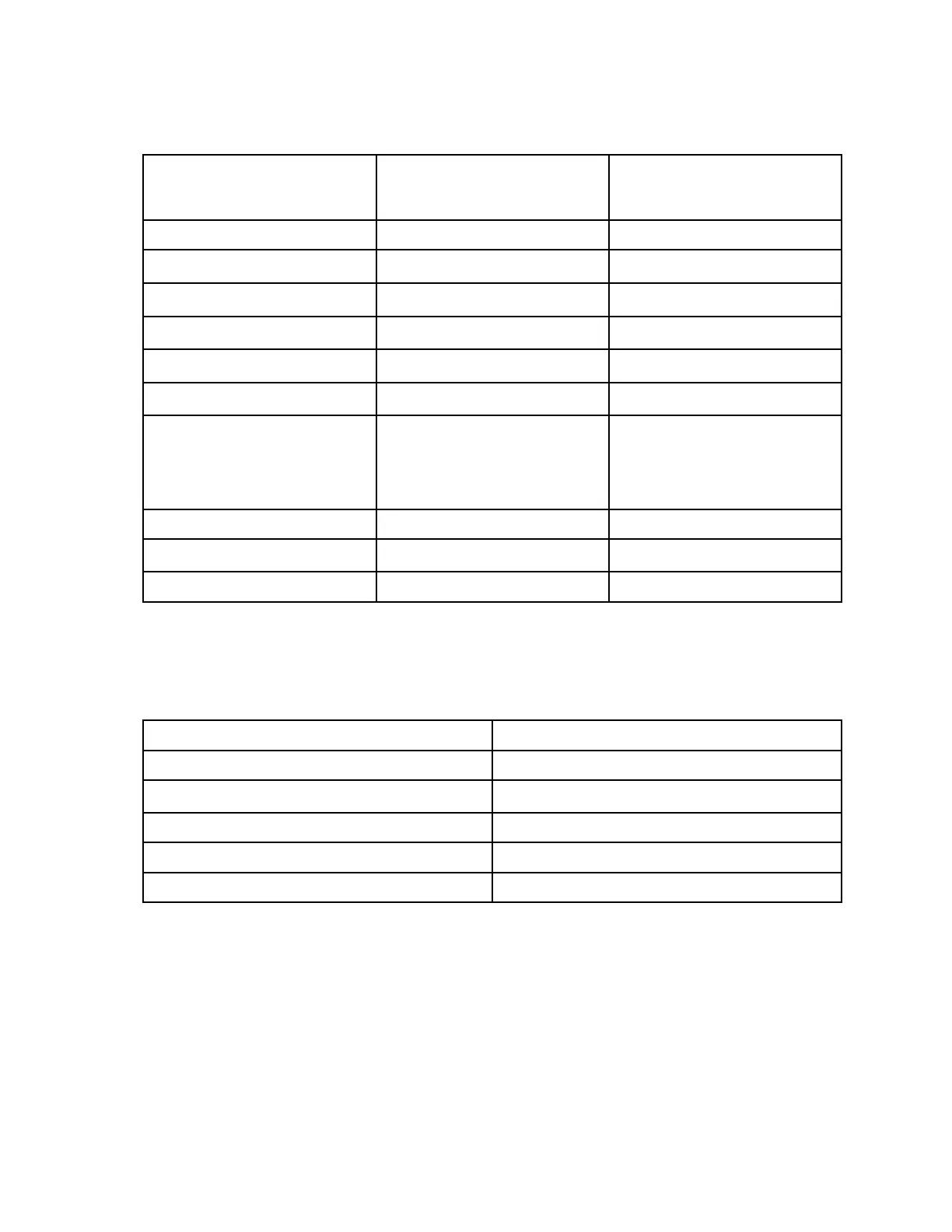
Fuses
Location Fuse
(Amps)
Circuit
F01 15 PTO
F02 5 Gauges / Slope Indicator
F03 5 Engine Run
F04 10 Head / Tail Lights
F05 10 Fuel Pump
F06 15* Work / Strobe Lights
F07 10 Speed Sensor /
Back-up / Horn /
Directional
F08 5 Tractor Control Module 1
F09 10** Diesel Stop
F10 15 Tractor Control Module 2
*Optional accessory
**4520Y only
Relays
Location Function
R01 PTO Out
R02 Fuel Pump
R03 -
R04 PTO In
R05 Starter
Electrical System: Electrical Component Testing Page 6–10 4520P
09.40003Rev 00