General Precautions for Removing and Installing
Hydraulic System Components (continued)
3. Remove all caps and plugs from the hydraulic lines, hoses, fittings and
components before connecting them again.
4. Use proper tightening procedures when installing the hydraulic components and
tightening hoses and fittings; refer to Installing the Hydraulic Hoses and Tubes
(O-Ring Face Seal), page 5–10 Installing the Hydraulic Fittings (SAE Straight
Thread O-Ring Fittings), page 5–12
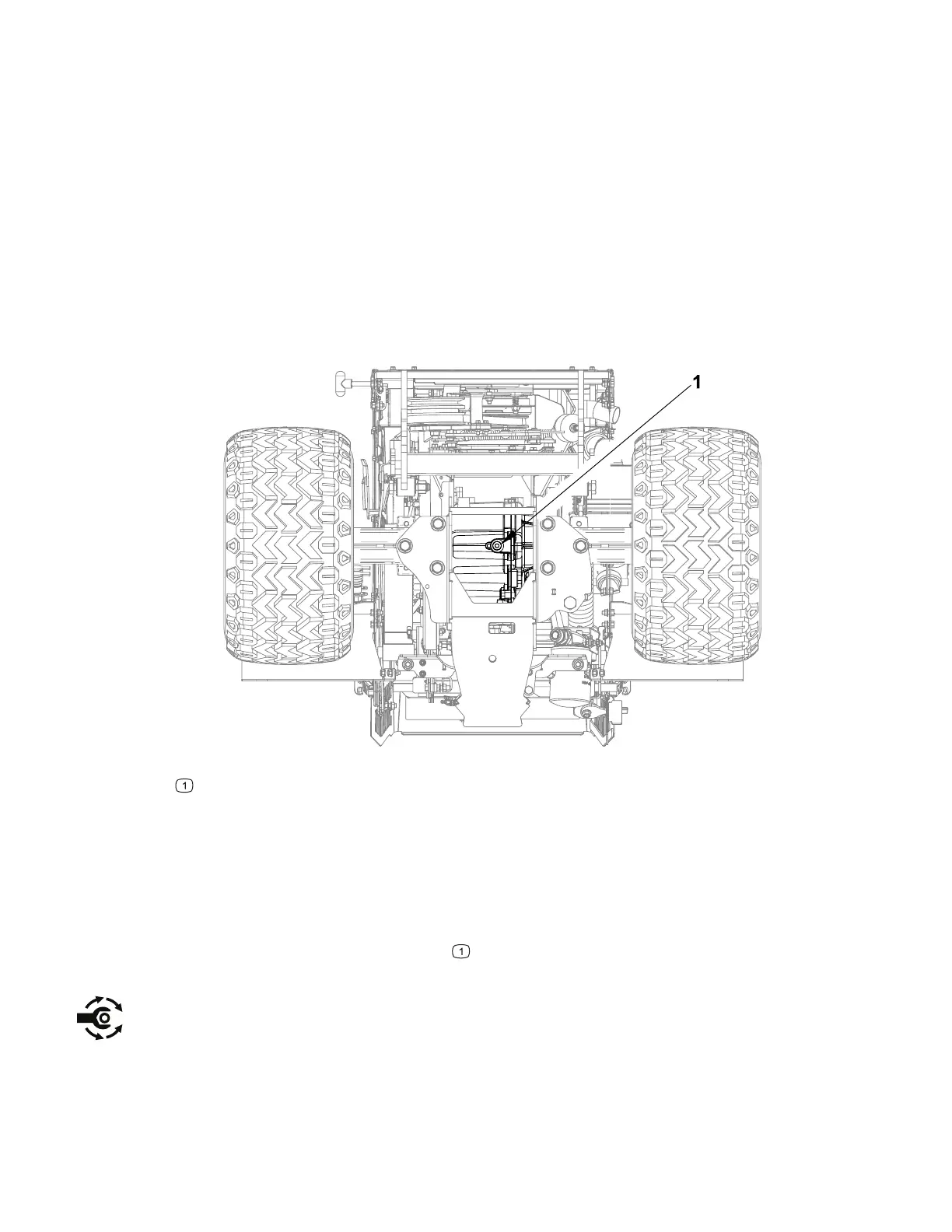
Changing the Hydraulic Fluid
Figure 29
G438986
Drain plug
1. Remove any attachments from the machine.
2. Park the machine on a level surface, engage the parking brake, and remove the
key from the ignition. Ensure that the steering is straight ahead, fully raise the
front hitch, fully lower the three point hitch (if equipped).
3. Place a drain pan (minimum 13.5 liters / 14 quarts) under the front transaxle.
4. Locate and remove the drain plug
from the front transaxle. Loosen the cap on
the hydraulic oil tank to allow the system to vent.
5. Replace the O-ring and install the drain plug 37 Nm (27 ft-lb).
6. Add hydraulic oil as specified in the Operator’s Manual to the hydraulic oil tank
until the oil level in the plastic site tube is within the proper range indicated by the
oil level decal.
Hydraulic System: Service and Repairs Page 5–20 4520P
09.40003Rev 00