Testing the Strobe Light Switch
1. Park the machine on a level surface, lower any attachments to the ground,
engage the parking brake, and remove the key from the ignition.
2. Switch the main circuit breaker to the O
FF position, to de-energize the electrical
system.
3. Remove the control panel from the right seat box; refer to Removing and
Installing the Control Panel, page 7–19.
4. Identify the strobe light switch and disconnect the wire harness connector from
the switch, remove the switch from the control panel if necessary.
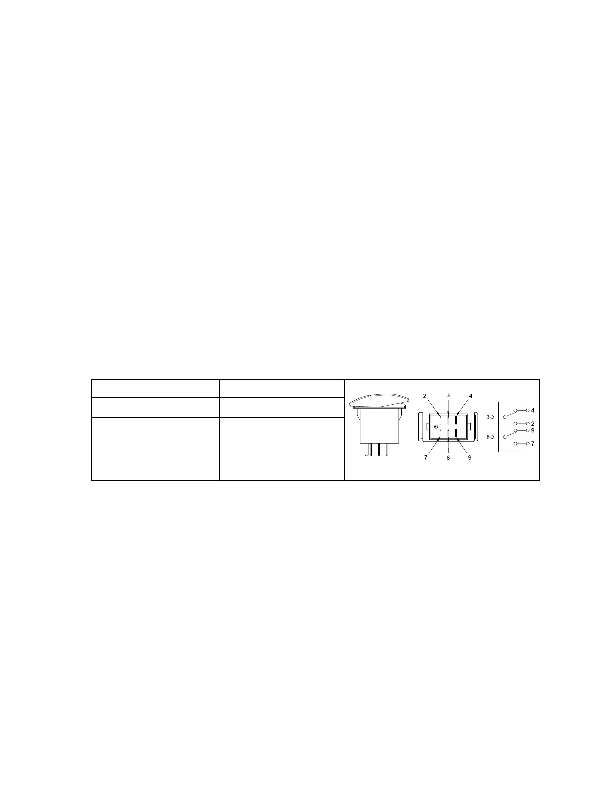
5. Use a multimeter (ohms setting) and the preceding table to determine whether
continuity exists between the terminals for each switch position.
6. Replace the switch if necessary.
7. If the switch tests correctly and a circuit problem still exists, check the wire
harnesses; refer to 9 Appendix A, page 9–1.
8. Install the switch, connect the wire harness, and install the control panel after
testing.
9. Switch the main circuit breaker to the O
N position, to energize the electrical
system.
Rear 12 Volt Switch
POSITION CLOSED CIRCUITS
G423468
REAR 12V ON 8 + 7
REAR 12V OFF NONE
The rear 12 volt switch is located on the right seat box. Pushing down on the left side
of the switch (toward the operator) provides power to the rear 12 volt 4 pin socket.
Pushing down on the right side of the switch (away from the operator) turns off power
to the 12 volt 4 pin socket.
Electrical System: Strobe Light Switch Page 6–36 4520P
09.40003Rev 00