Removing and Installing the Hydraulic Cooler Top
Cover (continued)
9. If the machine is equipped with a 3–point hitch, install the hydraulic valve
mounting bolts.
10. Tighten the hydraulic cooler top cover mounting bolts.
11. Install the control panel.
12. Switch the main circuit breaker to the O
N position, to energize the electrical
system.
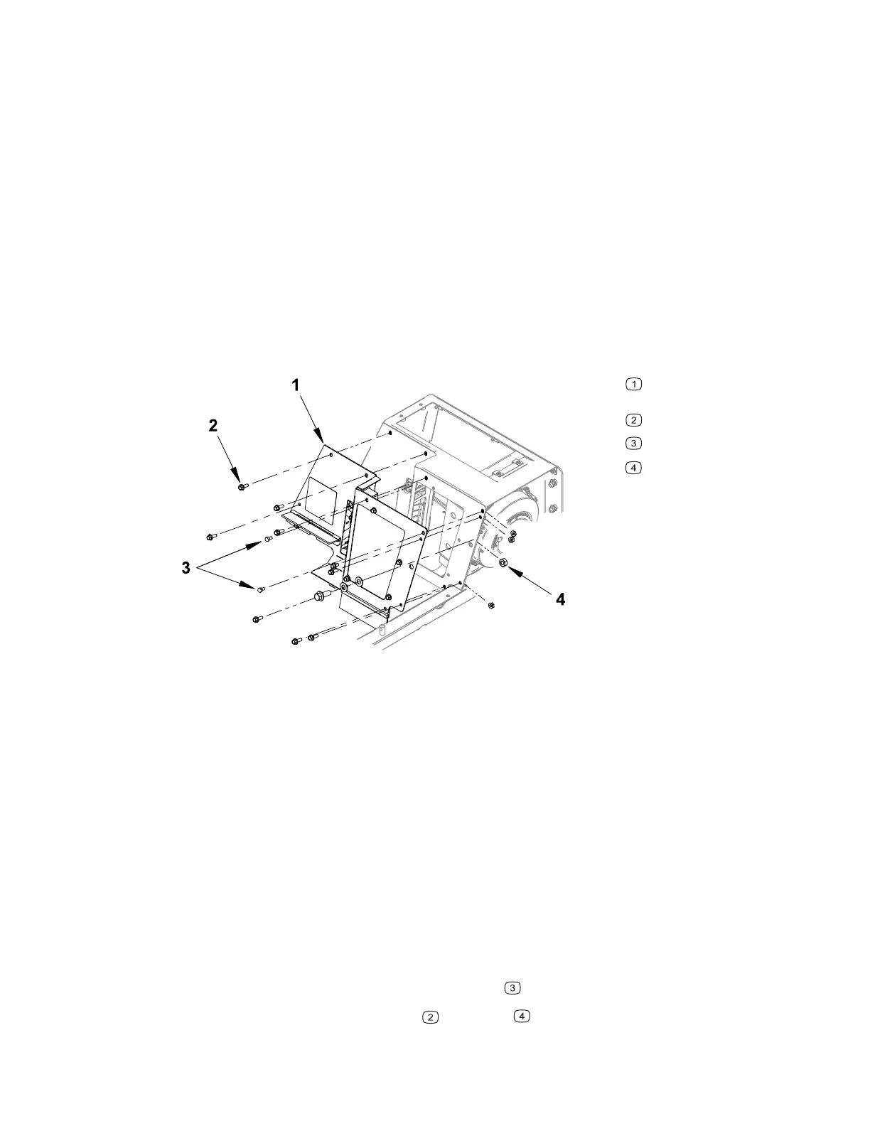
Removing and Installing the Hydraulic Cooler Inner
Cover
Figure 86
G430198
Inner hydraulic cooler
cover
Mounting bolt
Fuse panel mounting bolts
Nut
1. Park the machine on a level surface, lower any attachments to the ground,
engage the parking brake, and remove the key from the ignition.
2. Switch the main circuit breaker to the O
FF position, to de-energize the electrical
system.
3. Remove the control panel; refer to Removing and Installing the Control Panel,
page 7–19.
4. Remove the hydraulic cooler top cover; refer to Removing and Installing the
Hydraulic Cooler Top Cover, page 7–20.
5. Remove the SDLA pivot cover; refer to Removing and Installing the SDLA Pivot
Cover, page 7–22.
6. Locate label and disconnect the USB receptacle, rear 12–volt switch, and rear
12–volt momentary switch (if equipped) electrical connectors from the main
wiring harness.
7. Remove the fuse panel mounting bolts
.
8. Remove the mounting bolts
and nuts .
4520P Page 7–21 Chassis: Service and Repairs
09.40003Rev 00