Installing the Connector Link Mount (continued)
2. Apply red thread locker to the connector link mounting bolt threads. Install the
connector link mounting bolt.
3. Install the forward steering cylinder mounting bolt.
Removing the Center Pivot
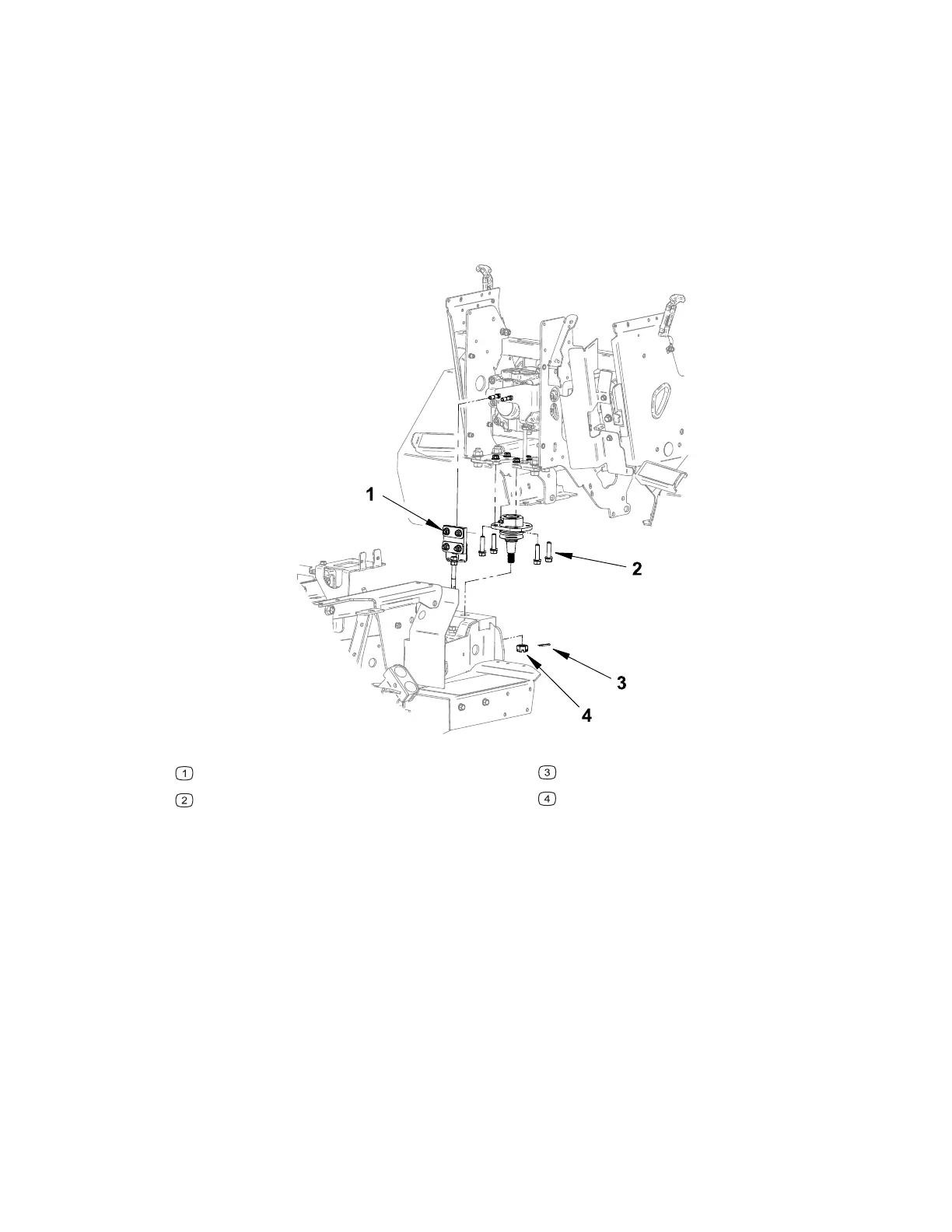
Figure 112
G445370
SDLA linkage
Mounting bolts
Cotter pin
Castle nut
1. Remove any attachments from the machine, park the machine on a level surface,
engage the parking brake, remove the key from the ignition, and switch the circuit
breaker to the O
FF position.
2. Remove the hydraulic pump cover; refer to Removing and Installing the Hydraulic
Pump Cover, page 7–15 and the lower frame cover; refer to Removing and
Installing the Lower Frame Cover, page 7–18.
3. Remove the front / rear connector link; refer to Removing the Front / Rear
Connector Link, page 7–46.
Chassis: Service and Repairs Page 7–48 4520P
09.40003Rev 00



 To Next Page