Drive Circuit (continued)
Hydraulic system pressure is generated by a piston-driven pump coupled to the
engine. This variable-displacement pump provides hydraulic flow under regulated
pressure to the front and rear drive motors and changes its fluid flow rate with an
internal swash plate. The swash plate angle is controlled by the SDLA control lever
through a linkage system. The angle of the swash plate determines the pump flow
rate and the speed of the machine. When the SDLA control lever is moved to its
fullest extension front or rear, the pump swash plate rotates fully to provide maximum
pump output flow and peak machine speed. With the engine running and the SDLA
control lever in the neutral position, the swash plate within the hydraulic pump is held
in the vertical position, providing no fluid flow to the front and rear drive motors, and
the machine remains stationary.
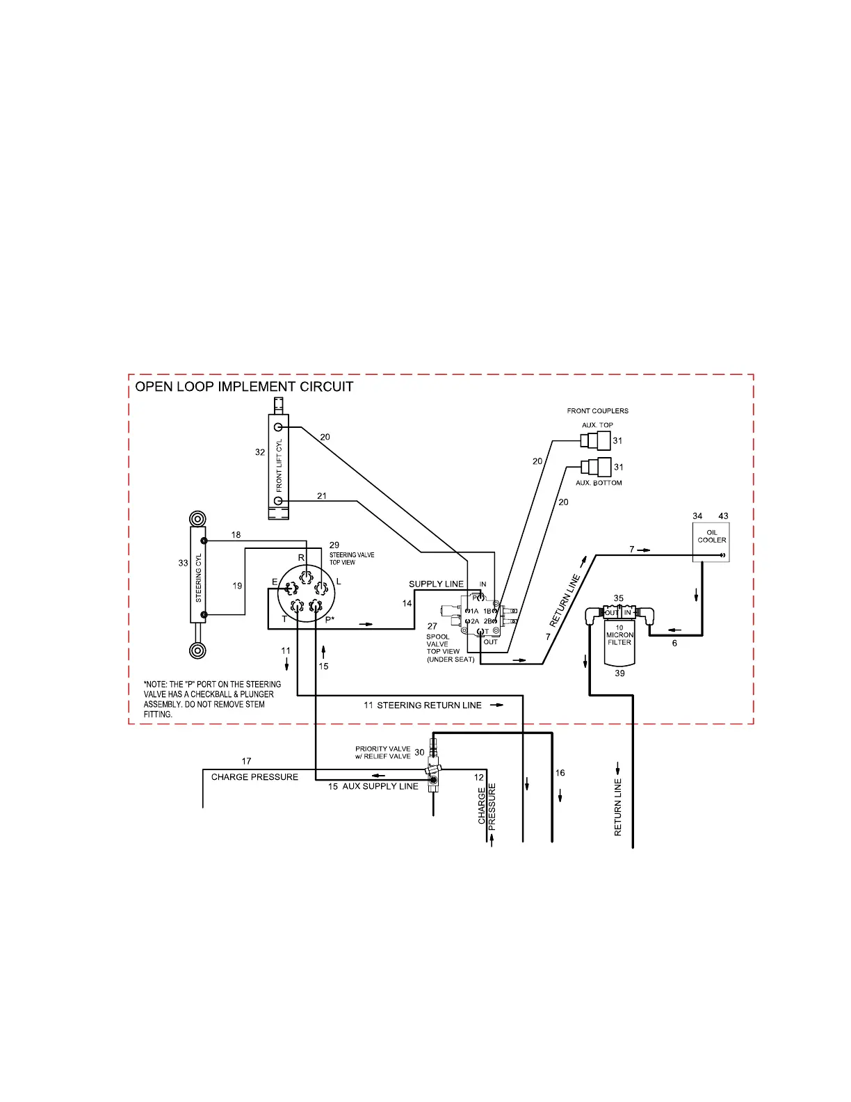
Implement Circuit
Figure 28
G446596
The implement circuit is an open-loop system that includes steering, lift, and auxiliary
operations. The charge pump supplies fluid flow for the circuit, charge pump output
flows first to the priority valve with a relief valve providing steering priority over lift and
auxiliary demand. From the priority valve fluid flows to the steering valve at P port. If
there is no steering, lift, or auxiliary input the fluid returns to the front transaxle
through the steering valve T port. Steering input directs fluid flow from P port to L or R
port, to the steering cylinder. Lift and auxiliary input directs fluid flow from P port to E
port, to the spool valve.
Hydraulic System: Hydraulic Flow Diagrams Page 5–18 4520P
09.40003Rev 00