Hydraulic Flow Diagrams
Drive Circuit
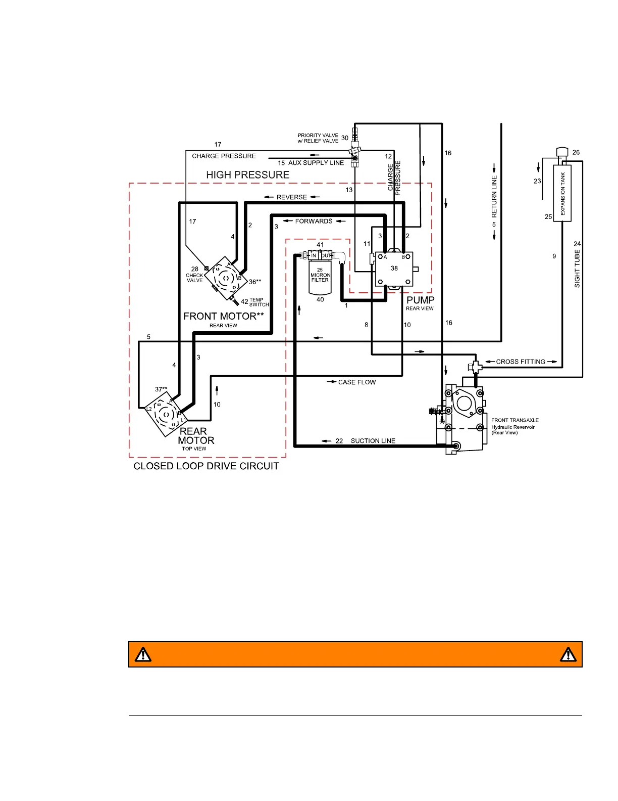
Figure 27
G446595
The drive circuit is a closed-loop system that includes 1 hydraulic pump and 2
hydraulic motors connected in series. In theory, oil never returns to the oil tank. Oil
circulates continuously from the hydraulic pump to the hydraulic motors and back to
the pump. Due to the pump and motor design, 5–10% of oil continually escapes into
the case of the pump and motors. The additional oil in the loop is necessary and is
supplied by the charge pump. Closed-loop circuits generally do not have in-loop
filtration. It is critical the closed-loop circuit is kept free of contamination. Every time
the closed-loop circuit is opened the remote filtering tool must be used to filter the
system before continuing the operation of the machine refer to; Remote Filtering the
Hydraulic System, page 5–3.
WARNING
Even small amounts of contamination can cause severe damage within the
closed-loop circuit.
4520P Page 5–17 Hydraulic System: Hydraulic Flow Diagrams
09.40003Rev 00