Figure 59
Littlefuse 55075
G426991
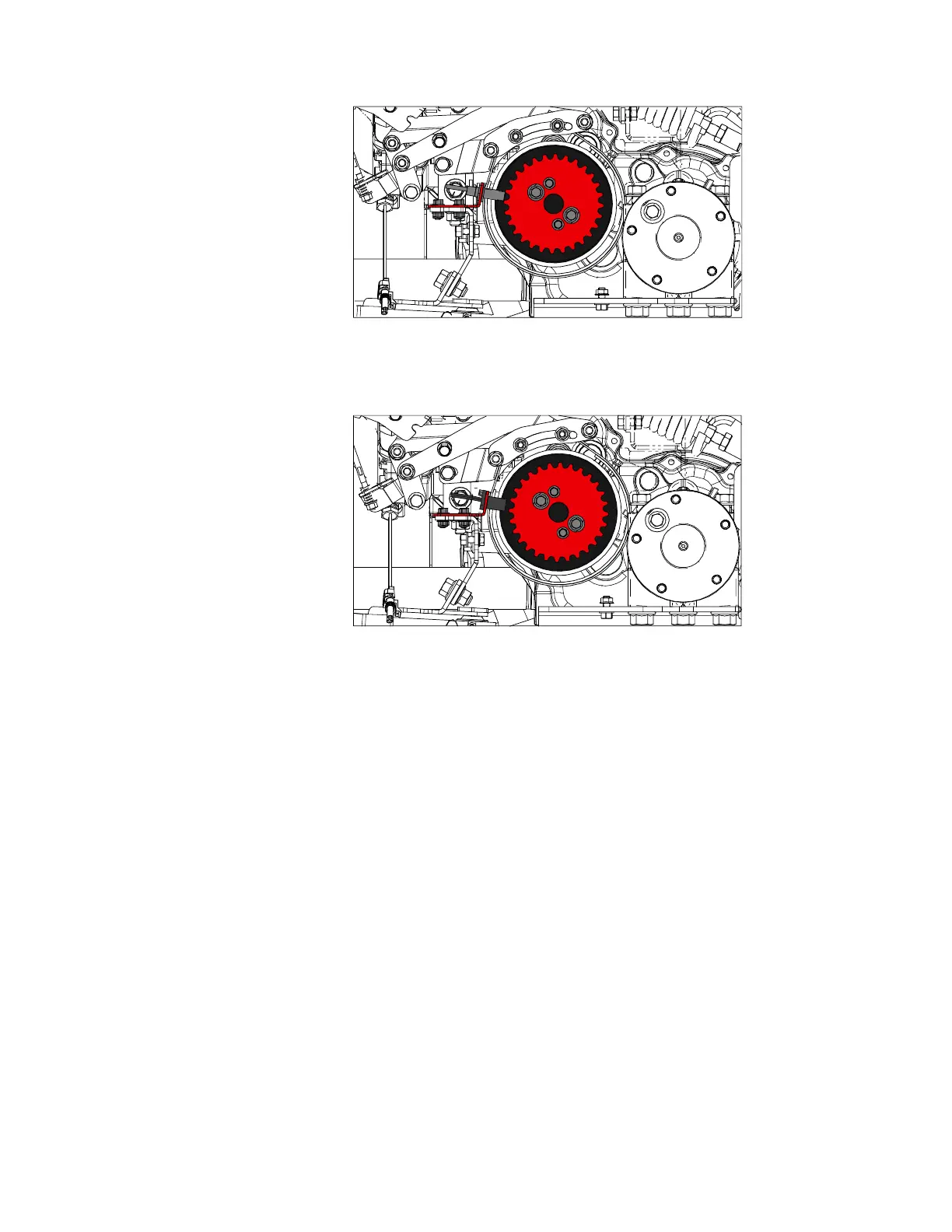
Figure 60
Littlefuse 55505
G426992
Testing the Speed Sensor
Testing the speed sensor requires the use of specialized equipment. In this procedure
visually inspect and clean the sensor then test the wiring harnesses.
1. Park the machine on a level surface, lower any attachments to the ground,
engage the parking brake, and remove the key from the ignition.
2. Switch the main circuit breaker to the O
FF position, to de-energize the electrical
system.
3. Disconnect and remove the sensor from the machine.
4. Clean the sensor and inspect the sensor for any damage. Replace the sensor if
the face is scratched or damaged in any way.
5. Test the machine wire harness to the speed sensor.
A. Switch the main circuit breaker to the O
N position, to energize the electrical
system.
B. Set the key switch to the R
UN position.
C. Use a multi meter set to DC voltage and check for approximately 12 VDC
across the supply (+) pin and (-) ground pin of the machine wire harness
speed sensor connector. This confirms the integrity of the circuit supply and
ground wires.
4520P Page 6–51 Electrical System: Speed Sensor
09.40003Rev 00