RPM Sensor
Figure 62
G422265
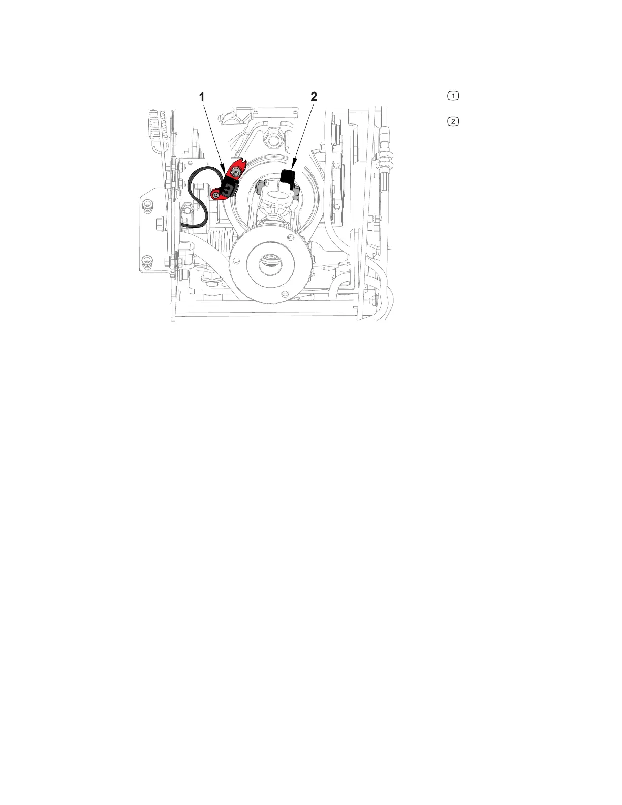
Ignition trigger RPM
sensor
Tach trigger plate
The RPM sensor is an ignition trigger that reports engine RPM. The ignition trigger is
mounted near the drive shaft, the drive shaft has a tach trigger plate that is bolted to
the pinch bolt. The tach trigger plate rotates with the drive shaft, each time the tach
trigger plate passes the ignition trigger the engine RPM is reported.
Testing the RPM Sensor
Testing the RPM sensor requires the use of specialized equipment. In this procedure
visually inspect and clean the sensor then test the wiring harnesses.
1. Park the machine on a level surface, lower any attachments to the ground,
engage the parking brake, and remove the key from the ignition.
2. Switch the main circuit breaker to the O
FF position, to de-energize the electrical
system.
3. Remove the radiator; refer to 4520P Removing the Radiator, page 4–15.
4. Disconnect and remove the sensor from the machine.
5. Clean the sensor and inspect the sensor for any damage. Replace the sensor if
the face is scratched or damaged in any way.
6. Test the machine wire harness to the RPM sensor.
A. Switch the main circuit breaker to the O
N position, to energize the electrical
system.
B. Set the key switch to the R
UN position.
C. Use a multi meter set to DC voltage and check for approximately 12 VDC
across the supply (+) pin and (-) ground pin of the machine wire harness
4520P Page 6–53 Electrical System: RPM Sensor
09.40003Rev 00