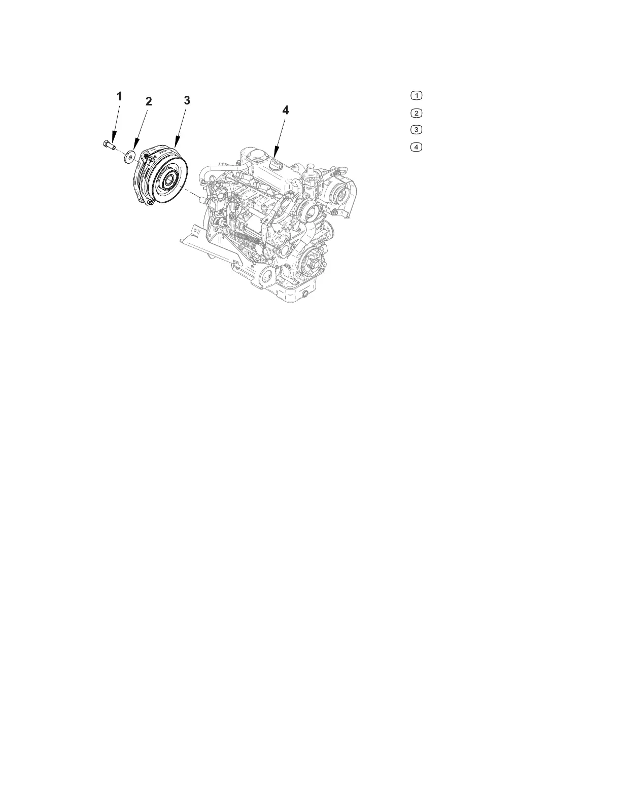
PTO Electric Clutch
Figure 53
G425950
Bolt
Washer
Electric clutch
Engine
An electric clutch is used to engage the PTO. The electric clutch is mounted on the
engine crankshaft and engages when current is applied to the clutch. The clutch also
incorporates a magnetic brake to stop the clutch rotation when the clutch is de-
energized.
Testing the PTO Electric Clutch
Before testing the PTO electric clutch check the PTO electric clutch air gap; refer to
Adjusting the PTO Electric Clutch Air Gap, page 7–4.
1. Park the machine on a level surface, lower any attachments to the ground,
engage the parking brake, and remove the key from the ignition.
2. Switch the main circuit breaker to the O
FF position, to de-energize the electrical
system.
3. Locate the PTO electric clutch on the engine crankshaft and disconnect the
clutch electrical connector from the main wiring harness.
Note: For accurate clutch resistance measuring, the clutch should be at
approximately 21°C (70°F).
Note: Before making small resistance readings with a digital multimeter, short the
multimeter leads together. The meter displays a small resistance value (usually 0.5
ohms or less). This resistance is because of the internal resistance of the multimeter
test leads. Subtract this value from the measured value of the component that you
are testing.
4. Use a multimeter (ohms setting) to check the clutch coil resistance between the
two terminals of the clutch electrical connector. The coil resistance should be
approximately 3.0 ohms. Additionally, check that there is no continuity between
either of the clutch wire connector terminals and the clutch frame.
Electrical System: PTO Electric Clutch Page 6–40 4520P
09.40003Rev 00