B.3 Parameter Table
YASKAWA ELECTRIC SIEP C710616 35D YASKAWA AC Drive E1000 Technical Manual 395
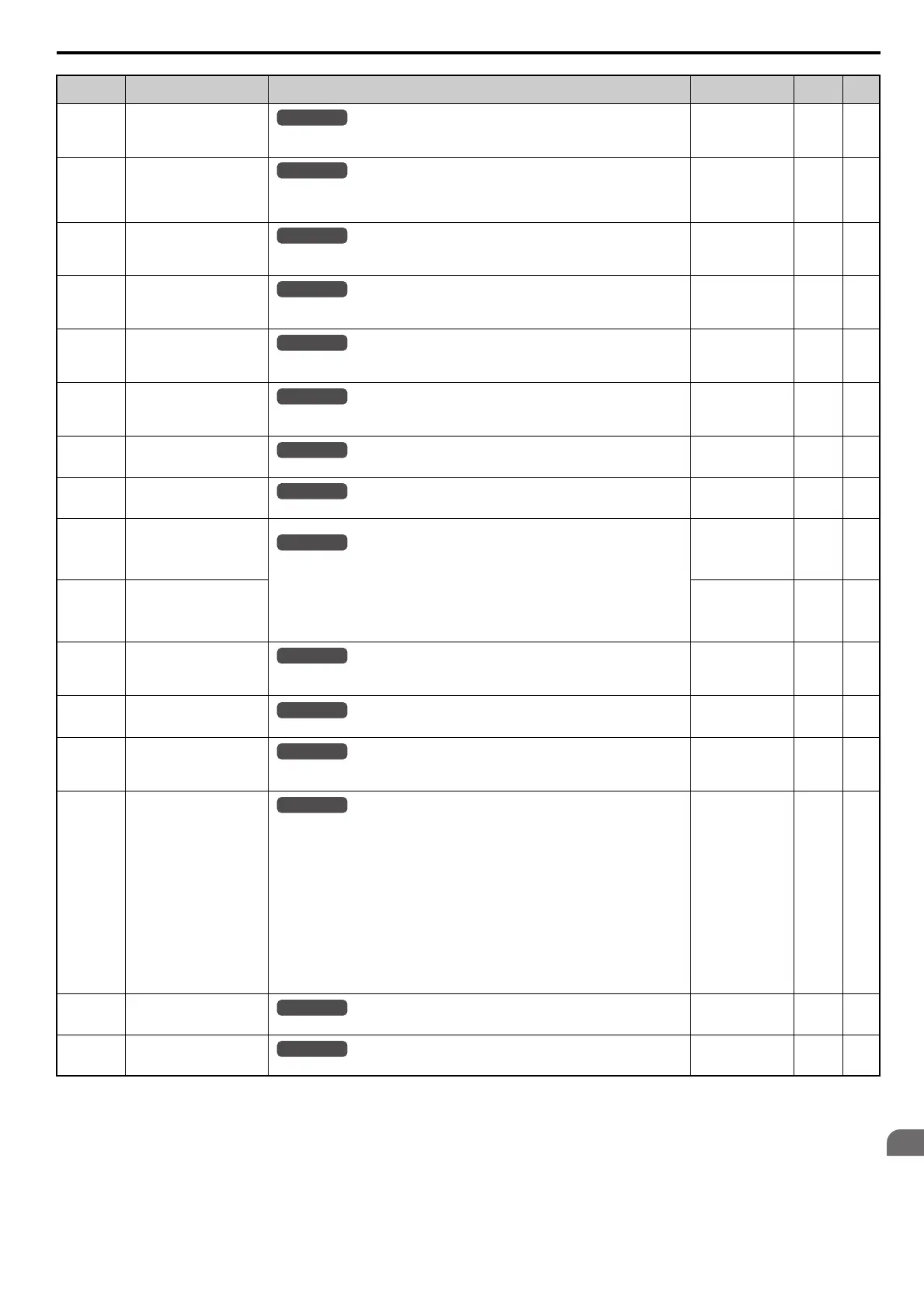
U4-02
(75H)
Number of Run Commands
Displays the number of times the Run command is entered. Reset the number of Run commands
using parameter o4-13. This value will reset to 0 and start counting again after reaching 65535.
No signal output
available
1 Time –
U4-03
(67H)
Cooling Fan Operation Time
Displays the cumulative operation time of the cooling fan. The default value for the fan
operation time is reset in parameter o4-03. This value will reset to 0 and start counting again
after reaching 99999.
No signal output
available
1 h –
U4-04
(7EH)
Cooling Fan Maintenance
Displays main cooling fan usage time in as a percentage of its expected performance life.
Parameter o4-03 can be used to reset this monitor.
No signal output
available
1% –
U4-05
(7CH)
Capacitor Maintenance
Displays main circuit capacitor usage time in as a percentage of their expected performance life.
Parameter o4-05 can be used to reset this monitor.
No signal output
available
1% –
U4-06
(7D6H)
Soft Charge Bypass Relay
Maintenance
Displays the soft charge bypass relay maintenance time as a percentage of its estimated
performance life. Parameter o4-07 can be used to reset this monitor.
No signal output
available
1% –
U4-07
(7D7H)
IGBT Maintenance
Displays IGBT usage time as a percentage of the expected performance life. Parameter o4-09
can be used to reset this monitor.
No signal output
available
1% –
U4-08
(68H)
Heatsink Temperature
Displays the heatsink temperature.
10 V: 100°C1°C–
U4-09
(5EH)
LED Check
Lights all segments of the LED to verify that the display is working properly.
No signal output
available
––
U4-10
(5CH)
kWh, Lower 4 Digits
Monitors the drive output power. The value is shown as a 9 digit number displayed across two
monitor parameters, U4-10 and U4-11.
Example:
12345678.9 kWh is displayed as:
U4-10: 678.9 kWh
U4-11: 12345 MWh
No signal output
available
1 kWh –
U4-11
(5DH)
kWh, Upper 5 Digits
No signal output
available
1 MWh –
U4-13
(7CFH)
Peak Hold Current
Displays the highest current value that occurred during run.
Note:The unit is 1 A in models CIMR-E4A0930 and 4A1200.
No signal output
available
0.01 A
<19> <50>
–
U4-14
(7D0H)
Peak Hold Output Frequency
Displays the output frequency when the current value shown in U4-13 occurred.
No signal output
available
0.01 Hz –
U4-16
(7D8H)
Motor Overload Estimate
(oL1)
Shows the value of the motor overload detection accumulator. 100% is equal to the oL1
detection level.
10 V: 100% 0.1% –
U4-18
(7DAH)
Frequency Reference Source
Selection
Displays the source for the frequency reference as XY-nn.
X: indicates which reference is used:
1 = Reference 1 (b1-01)
2 = Reference 2 (b1-15)
Y-nn: indicates the reference source
0-01 = Digital operator
1-01 = Analog (terminal A1)
1-02 = Analog (terminal A2)
1-03 = Analog (terminal A3)
2-02 to 17 = Multi-step speed (d1-02 to 17)
3-01 = MEMOBUS/Modbus communications
4-01 = Communication option card
5-01 = Pulse input
7-01 = DWEZ
No signal output
available
––
U4-19
(7DBH)
Frequency Reference from
MEMOBUS/Modbus Comm.
Displays the frequency reference provided by MEMOBUS/Modbus (decimal).
No signal output
available
0.01% –
U4-20
(7DCH)
Option Frequency Reference
Displays the frequency reference input by an option card (decimal).
No signal output
available
––
No. (Addr.) Name Description
Analog Output
Level
Unit Page
All Modes
All Modes
All Modes
All Modes
All Modes
All Modes
All Modes
All Modes
All Modes
All Modes
All Modes
All Modes
All Modes
All Modes
SIEP_C710616_35.book 395 ページ 2015年11月30日 月曜日 午後2時2分