Chapter 5 Connecting User-Supplied Digital I/O Equipment
Adept MV Controller User’s Guide, Rev. B 115
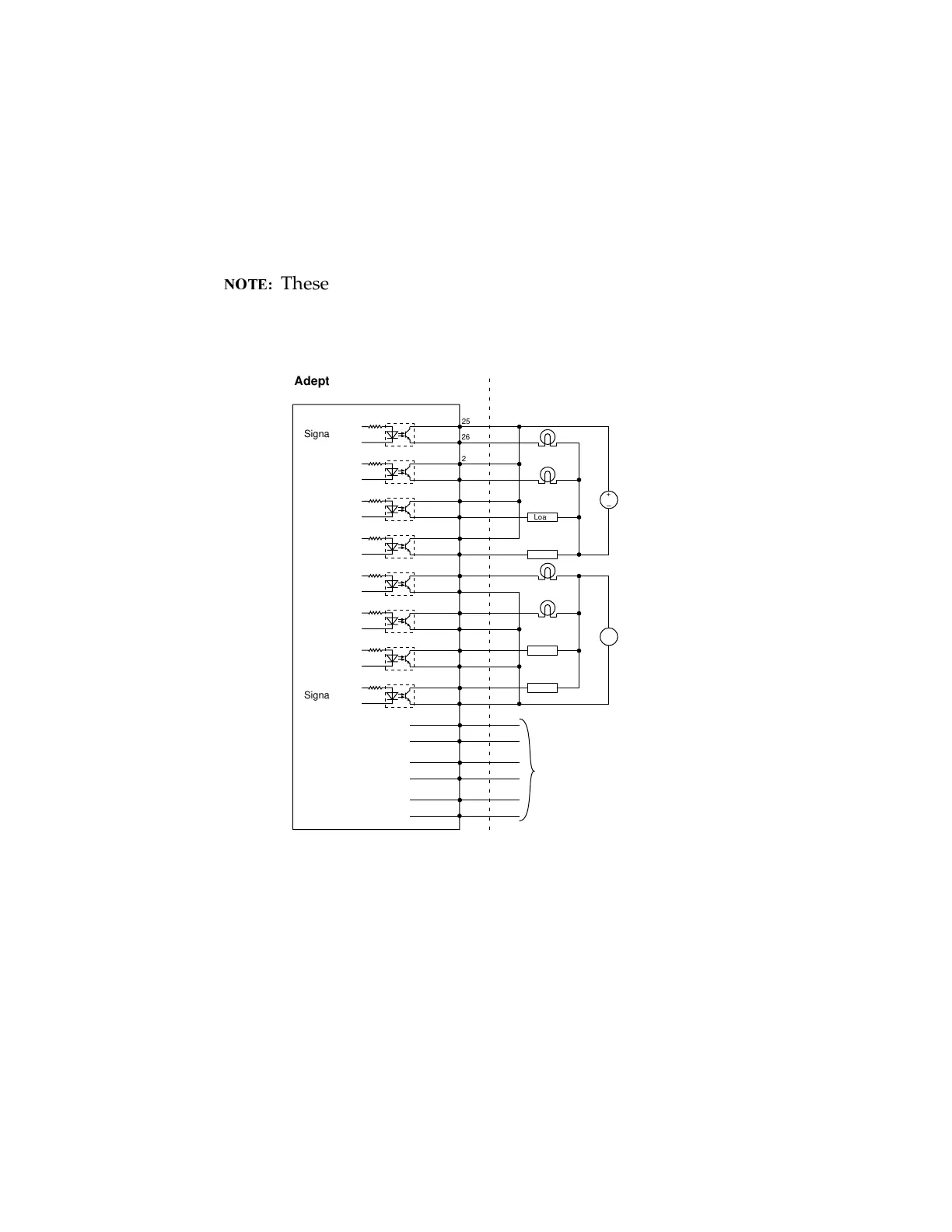
The following drawing shows two examples of different connections to the digital
outputs on the JSIO connector. The examples are negative common and positive
common.
Example 1: outputs 0001 to 0004 are shown with positive common.
Example 2: outputs 0005 to 0008 are shown with negative common.
These are examples. Either method can be used, in any
combination, on any channel.
Figure 5-10. Digital Output Wiring for JSIO Connector
User power
supply
Example 1
Example 2
User power
supply
Signal 0001
(equivalent circuit)
Signal 0002
Signal 0003
Signal 0004
Signal 0005
Signal 0006
Signal 0007
EMERGENCY
STOP
CONNECTIONS
See chapter 3 for a description
of Emergency
Stop Circuit
Signal 0008
+
–
Adept-Supplied Equipment User-Supplied Equipment
(Typical Examples)
+
–
Load
Load
Load
Load
JSIO Digital I/O Connector on the CIP - Outputs
25
26
27
28
29
30
31
32
33
34
35
36
37
38
39
40
41
42
43
44
45
46
+
–
+
–
+
–
+
–
+
–
+
–
+
–
+
–
Sourcing
Sinking
Adept-Supplied Equipment
User-Supplied Equipment
(Typical Examples)
Example 1
Sourcing
User Power
Supply
Example 2
Sinking
User Power
Supply
Emergency
Stop
Connections
See 3)
- for details
JSIO Digital I/O Connection on the CIP - Outputs
Artisan Technology Group - Quality Instrumentation ... Guaranteed | (888) 88-SOURCE | www.artisantg.com