Chapter 7 Camera Cables
Adept MV Controller User’s Guide, Rev. B 149
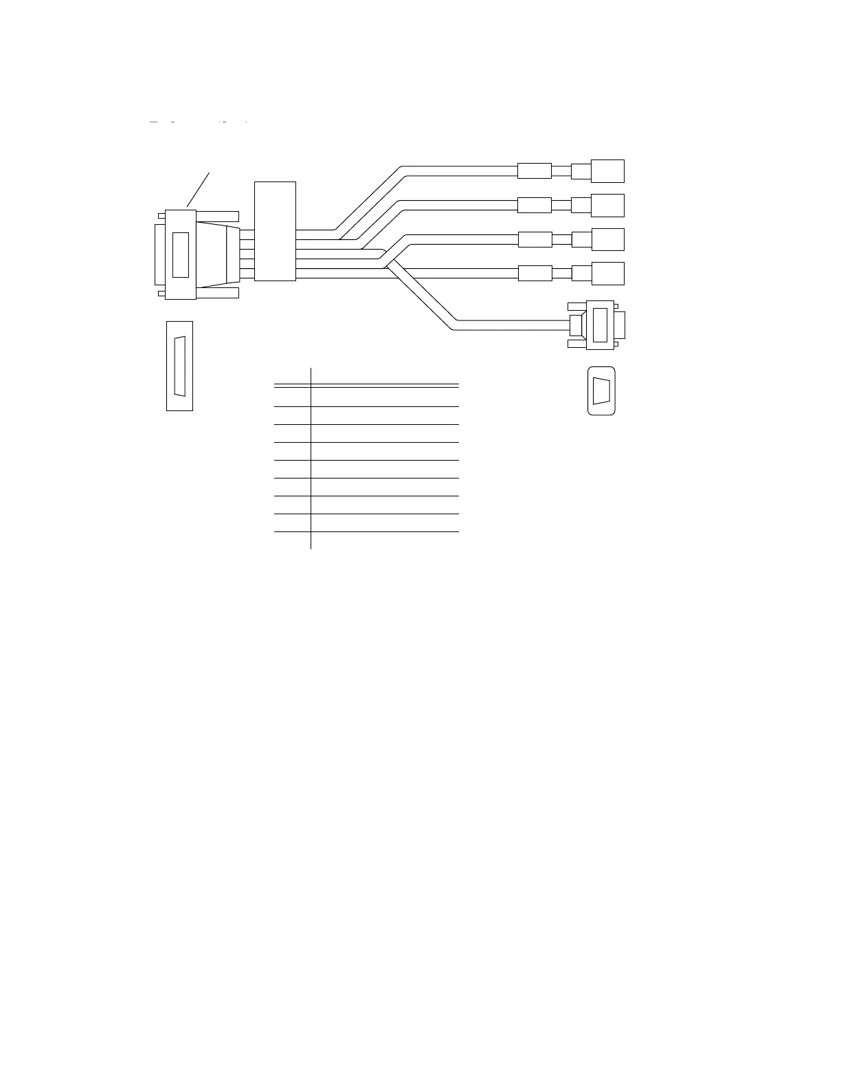
Figure 7-5. Custom Breakout Cable for Pulnix TM-1001
ADEPT
CABLE ASSY. CAMERA
INTERFACE 4X
CAM 1
CAM 2
1
31
15
44
CAM 3
CAM 4
5
9
1
6
D-sub
Auxiliary
Connector
To Camera/Strobe
connector on
EVI module
Pin Signal
1 User +12V to cameras
2 User power return
3 Strobe 1
4 Strobe return
5 Strobe 2
6 Frame Reset 1
7 Frame Reset return
8 Frame Reset 2
9 Shield (chassis ground)
D-sub Auxiliary Connector
Pin Assignments
To Camera/Strobe
connector on EVI
board
To Camera/Strobe
connector on EVI
board
D-sub Auxiliary Connector Pin Assignments
Pin Signal
1 User +12V to cameras
2 User power return
3 Strobe 1
4 Strobe return
5 Strobe 2
6 Frame Reset 1
7 Frame Reset return
8 Frame Reset 2
9 Shield (chassis ground)
D-sub
Auxiliary
Connector
Artisan Technology Group - Quality Instrumentation ... Guaranteed | (888) 88-SOURCE | www.artisantg.com