Chapter 8 Serial I/O Connectors
Adept MV Controller User’s Guide, Rev. B 171
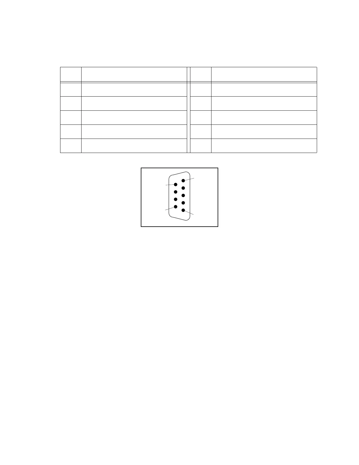
Figure 8-1. RS-232 Serial I/O Connector Pin Locations on SIO Board
Table 8-1. RS-232 Serial I/O Connector Pin Assignment on SIO Board
Pin Signal Name Pin Signal Name
1 not used 6 DSR (Data Set Ready)
2 RXD (From Device) 7 RTS (Request to Send)
3 TXD (To Device) 8 CTS (Clear to Send)
4 DTR (Data Terminal Ready) 9 not used
5 SG (Signal Ground)
Pin 1
Pin 5
Pin 6
Pin 9
Artisan Technology Group - Quality Instrumentation ... Guaranteed | (888) 88-SOURCE | www.artisantg.com