Chapter 10 Belt Encoder Interface
Adept MV Controller User’s Guide, Rev. B 185
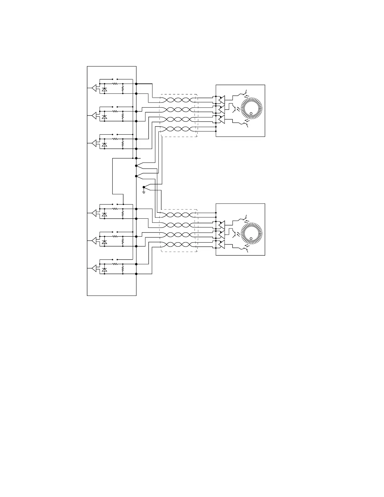
Figure 10-2. EJI Belt Encoder Typical Input Circuity
Encoder
+
–
RP8
RP7
RP6
HCPL
2231
VJI/EJI
Encoder Channel 1
Encoder Channel 2
RP8
RP7
RP6
HCPL
2231
RP8
RP7
Shield
(see
Note 2)
Enc. Gnd
Enc. Pwr
Pull up
RP6
HCPL
2231
Note 1:
RP6 & RP9: 330Ω, 6-pin resistor pack, socketed
RP7 & RP10: 470Ω, 6-pin resistor pack, socketed
RP8 & RP11: 470Ω, 6-pin resistor pack, socketed
For single-ended encoders, remove RP7 and RP10,
and install RP8 and RP11.
HCPL2231: Hewlett-Packard Opto-coupler
Note 2: Connect cable shield to connector shell.
A–
A+
B+
B–
I+
I–
For normal differential operation on channel 1,
RP8 is not installed.
For normal differential operation on channel 2,
RP11 is not installed.
Encoder
+
–
RP11
RP10
RP9
HCPL
2231
RP11
RP10
RP9
HCPL
2231
RP11
RP10
RP9
HCPL
2231
A–
A+
B+
B–
I+
I–
Encoder power output: 5V at 800 mA max. (1 A fuse)
EJI
For normal differential operation on channel 1,
RP8 is not installed
Encoder power output: 5V at 800mA max. (1 A fuse)
For normal differential operation on channel 2,
RP11 is not installed
Note 2:
RP6 & RP9: 300Ω, 6-pin resistor pack, socketed
RP7 & RP10: 470Ω, 6-pin resistor pack, socketed
RP8 & RP11: 470 Ω, 6-pin resistor pack, socketed
For single-ended encoders, remove RP7 and RP10,
and install RP8 and RP11.
HPCL2331: Hewlett-Packard Opto-coupler
Encoder Channel 2
Encoder Channel 1
Note 2: Connect cable shield to
connector shell
Artisan Technology Group - Quality Instrumentation ... Guaranteed | (888) 88-SOURCE | www.artisantg.com