Chapter 12 Outputs
Adept MV Controller, User’s Guide, Rev. B 197
case, a minimum of 4 power pins should be used. Nine power pins are provided
to allow for more wire connections to decrease the voltage drop across the power
supply wires. If you experience an excessive voltage drop, make connections to
additional power pins (to a maximum of 9).
The ground connection should connect to the power supply directly, not to the
ground connection of the load. This will isolate the board from any voltage drop
across the load ground wires.
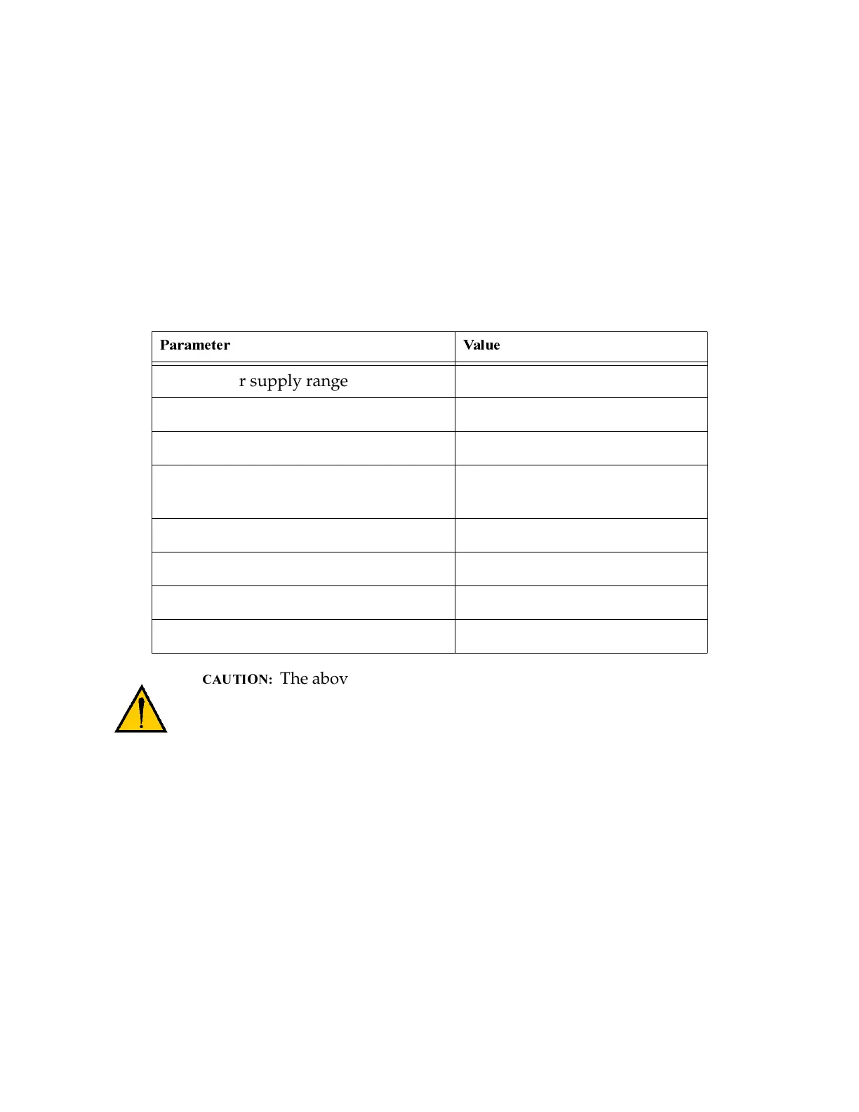
The above specs apply only to the output channels on the
DIO board. See Chapter 8 for specs on the digital output channels
on the SIO board. See Chapter 5 for specs on the digital output
channels on the CIP.
Table 12-3. Digital Output Circuit Specifications
Low power supply range 10 VDC ≤ V
sup
≤ 15 VDC
High power supply range 15 VDC ≤ V
sup
≤ 30 VDC
Power supply ground current I
g
≤ 35 mA
Operational current range, per
channel
I
out
≤ 400 mA
V
out
, output on, I
out
= 400 mA V
sup
– 0.8 ≤ V
out
≤ V
sup
Output off leakage current I
out
≤ 400 µA
Turn on response time 10 µsec maximum
Turn off response time 120 µsec maximum
Artisan Technology Group - Quality Instrumentation ... Guaranteed | (888) 88-SOURCE | www.artisantg.com