Chapter 12 Typical DIO Wiring
Adept MV Controller, User’s Guide, Rev. B 199
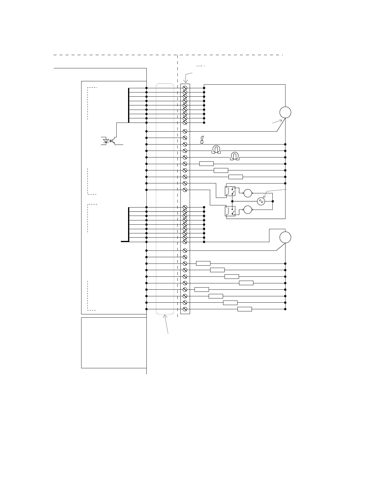
Figure 12-2. Typical Digital Output Setup
M
Adept-Supplied Equipment
User-Supplied Equipment
25
User DC
Power
Supply
+
–
DIO Module
Output Group 1
Wiring
Terminal
Block
Typical User Loads
P3 Connector – 44-Pin Female D-Sub
Output Group 3
Signals 0049 – 0056
Output Group 4
Signals 0057 – 0064
P4 Connector –
44-Pin Female D-Sub
Adept Digital Output
Cable (optional)
26
38
39
40
41
42
43
44
28
Group 1 Return
29
Group 1 Test
30
Signal 0033
15
Signal 0034
14
Signal 0035
13
Signal 0036
12
Signal 0037
11
Signal 0038
10
Signal 0039
9
Signal 0040
Load
17
User AC
Power
Supply
+
–
18
19
31
32
33
34
35
36
21
Group 2 Return
22
Group 2 Test
7
Signal 0041
6
Signal 0042
5
Signal 0043
4
Signal 0044
3
Signal 0045
2
Signal 0046
1
Signal 0047
16
Signal 0048
M
User DC
Power
Supply
Connect module
power return
directly to power
supply if possible.
Load
Load
Load
Load
Load
Load
Load
Load
Load
Load
Output Group 2
Group 1
Power Pins
(see text)
Group 2
Power Pins
(see text)
L
N
(equivalent
circuit)
Adept-Supplied Equipment
Wiring Terminal
Block
P3 Connector - 44-Pin Female D-Sub
User-Supplied Equipment
Group 1
Power Pins
(see text)
Connect module
power return directly
to power supply if
possible
User DC
Power
Supply
Input Group 1Input Group 2
User DC
Power
Supply
User AC
Power
Supply
P4 Connector - 44-Pin
Female D-Sub
DIO Board
Typical User Loads
Group 2
Power Pins
(see text)
(equivalent
circuit)
Output Group 3
Signals 0049 - 0056
Output Group 4
Signals 0057 - 0064
Adept Digital Output Cable
(optional)
Artisan Technology Group - Quality Instrumentation ... Guaranteed | (888) 88-SOURCE | www.artisantg.com