Appendix G DeviceNet Physical Layer and Media
Adept MV Controller User’s Guide, Rev. B 389
It is important to note that voltage differences between the V– and V+ conductors
need to be between 11V and 25V. The common-mode voltage between any two
places on the V– wire must not exceed 5V.
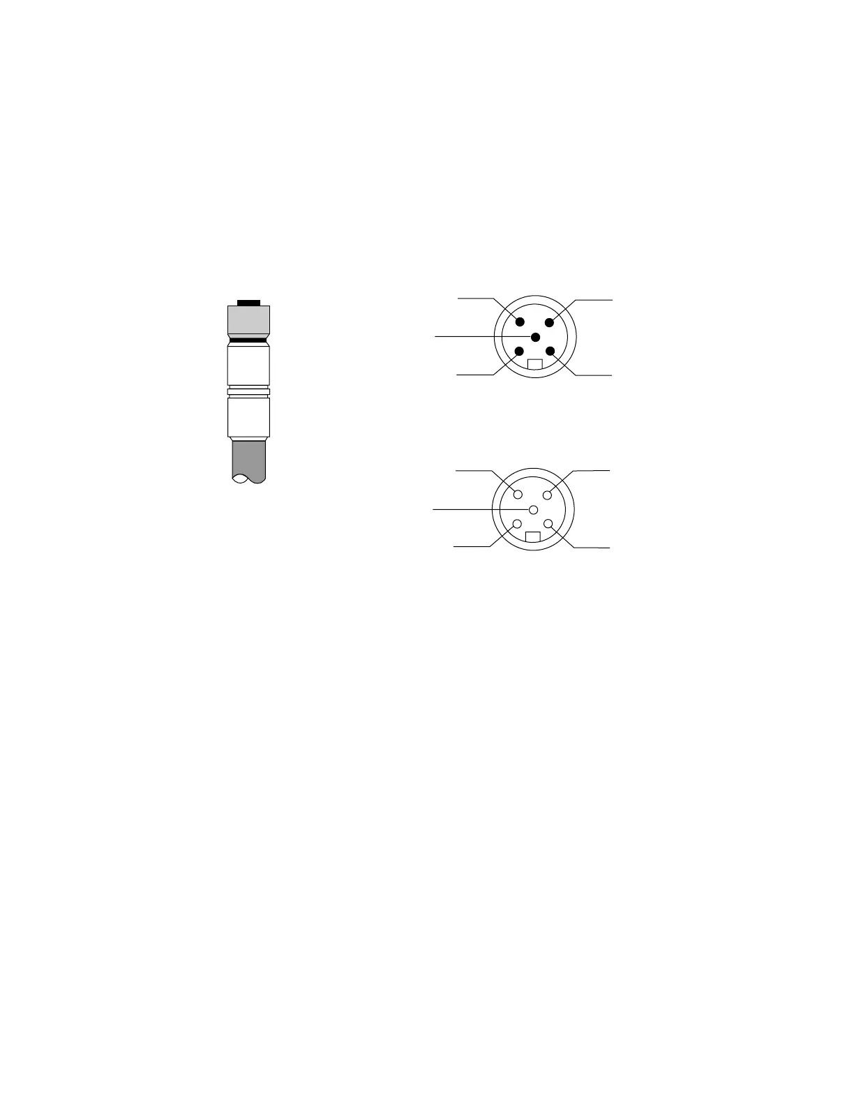
Figure G-6. DeviceNet Connector Pinouts
Male Connector (pins)
Female Connector (sockets)
4
3
5
1
2
3
5
2
4
1
Micro-Style
Connector
LEGEND:
1 Drain (bare)
2 V+ (red)
3 V- (black)
4 CAN_H (white)
5 CAN_L
blue
(VIEWED FROM CONTACT END)
Artisan Technology Group - Quality Instrumentation ... Guaranteed | (888) 88-SOURCE | www.artisantg.com