General Information
3
PN 4004700–ENG Rev. K
Display
Display Hardware
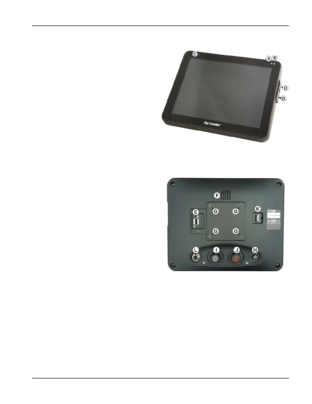
Front side
A. Light sensitivity sensor—Used to automatically
dim the display during night-time or low-light
situations.
B. Power light—The power light displays one of three
states:
C. Built in lightbar—for guidance
Side
D. Side mount USB media slots
(2 slots for 1200, 1 slot for 800)
Used for data transfer in and out of the display.
Used to charge mobile devices up to 1.2 amps.
Rear
E. WiFi—802.11 communication
F. Speaker—The built-in speaker is used for audible
warnings. The volume can be adjusted through the
display setup routine.
G. Mounting bracket
H. Power/Reset switch
The Power/Reset switch is used for turning the display
on and off in installations where the system is
connected to a continuous power supply.
If the display ever stops responding, the manual power
switch may be held in for five seconds to restart the
system. Only do this as a last resort, data loss could
occur during times of improper shutdown.
I. 19-pin auxiliary connection—Used for camera input.
J. 19-pin plug—The 19-Pin round display connector contains CAN, RS-232 serial, and system power and ground
connections. It is compatible with some certain other displays.
K. HDMI OUT (1200 only)
L. Ethernet Connection—4-pin connection used for communication with ParaDyme, GeoSteer, SteerCommand®,
OnTrac3™
Installation Instructions
All machine installation and mounting kits are shipped with instructions specific to that kit. Instructions include special
details relating to mounting, wiring and display configuration.
Mount the display securely inside the vehicle cab. The following must be considered when choosing a mounting location:
Green = ON
Pulses amber = Standby Mode
Solid amber = Running on battery power