4
• The display must be readily accessible to the
machine operator.
• The display must not obstruct the machine
operator's normal driving view.
• The display must not interfere with or limit
access to any of the existing machine controls.
• The CAN system cabling must be routed and
secured without interfering with existing
machine controls.
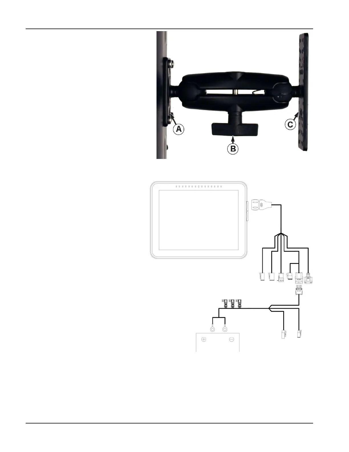
(A) RAM Base
(B) RAM Arm
(C) Base
€
DANGER!: If drilling holes is required during the
mounting process, care must be taken to
insure that damage is not done to existing
vehicle wiring, mechanical, or cab structure. Refer to vehicle manufacturer documentation for specific details on
equipment. Follow all OEM instructions, cautions, and warnings when working around equipment.
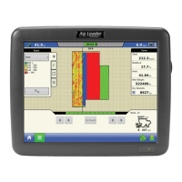
Fuse Installation and
Replacement
Fuse Type: Blade Style (ATO/ATC)
Rating:
• Fuse Holder (orange wire) 7.5A, 250 VAC
• Fuse Holder (pink wire) 15A, 250 VAC
• Fuse Holder 30A, 250 VAC
The fuse is to be placed in the fuse holder in-line
with the battery power cable and used with
display only.
CAN A
Power
Guidance
Activation
Guidance
Power
High Current
Power