Protected by copyright. Copying for private or commercial purposes, in part or in whole, is not
permitted unless authorised by AUDI AG. AUDI AG does not guarantee or accept any liability
with respect to the correctness of information in this document. Copyright by AUDI AG.
72 mm Diameter Hydraulic Mount, Installing (Caster Adjusting
Bolt Connection)
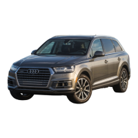
– Using, for example, a felt-tipped pen, draw an extension of the
relief notch on the outer diameter of the bonded rubber bush‐
ing.
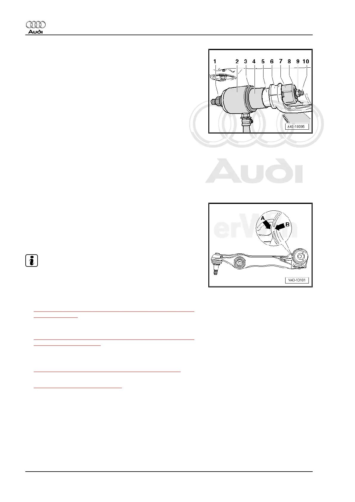
– Attach tools onto lower control arm, as shown in illustration.
1 - Nut - T10230/2-
2 - Hydraulic Press - VAS6178-
3 - Thrust Plate - T10230/7-
4 - Tube - T10230/9-
5 - Bonded Rubber Bushing
6 - Lower Control Arm
7 - Thrust Piece - T10230/16-
8 - Washer
9 - Nut - T10230/2-
10 - Threaded Spindle - T10230/1-
Align bonded rubber bushing to marking -arrow- and press in until
stop.
• Arrow -A- - Seam edge in casting of control arm
• Arrow -B- - relief notch in the bonded rubber bushing
– Install control arm to subframe.
Note
♦
Bonded rubber bushings can only be turned to a limited extent.
Only tighten suspension screws when vehicle is in curb weight
or control position.
♦
Wheel bearing, lifting to curb weight position on vehicles with
coil springs, refer to
⇒ “1.4 Wheel Bearing in Curb Weight, Lifting Vehicles with Coil
Spring”, page 12 .
♦
For vehicles with air spring suspension, lift wheel suspension
in control position, refer to
⇒ “1.5 Wheel Bearing in Control Position, Lifting Vehicles with
Air Suspension”, page 14 .
– On vehicles with air suspension, position vehicle on wheels,
refer to
⇒ “4 Positioning Vehicle on Hoist and Wheels”, page 10 .
– An axle alignment may be required. Refer to
⇒ “5 Wheel Alignment”, page 247 .
Checking and aligning front/rear axle must take place on a VW/
Audi recommended alignment stand.
Audi Q7 2007 ➤
Suspension, Wheels, Steering - Edition 01.2014
90 Rep. Gr.40 - Front Suspension


 To Next Page