82.3-0000010 OM
136
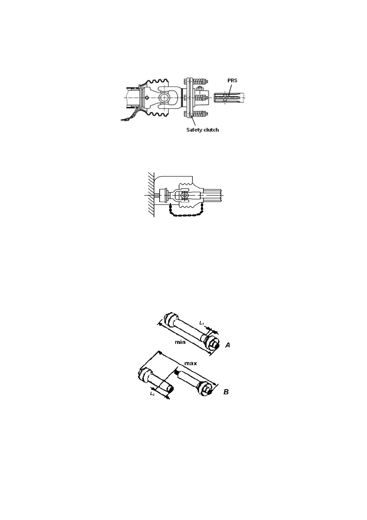
6. Safety clutch, as indicated in figure 4.9.2, shall be installed only from the side of
the PRS of the machine drive, other method of installation will not ensure timely protection
of the tractor PTO shaft from the excess of maximum permissible torque. After lengthy
downtime of the machine, check the implement safety clutch technical condition.
Figure 4.9.2 – Safety clutch installation scheme
7. Mounting of the cardan shaft with guard housing along with protective devices of
the PTO and PRS, with retaining chains both from the side of the PTO shaft and of the
PRS, as indicated in figure 4.9.3, ensures cardan joint safety.
Figure 4.9.3 – Safe cardan shaft mounting scheme
8. When the cardan shaft is used for the first time it is necessary to check the car-
dan shaft length, and to adjust it to the operating conditions with the BELARUS-82.3 trac-
tors when needed. For more detailed guidelines on cardan shafts see the technical docu-
mentation attached to the machine. Contact the cardan shaft manufacturer when needed.
9. The length of the cardan shaft maximum driven apart (which is permitted for op-
eration) shall be of such type when the one part of the cardan shaft enters another for not
less than L
2
=150 mm. If the value is below L
2
=150 mm (figure 4.9.4, view А) the cardan
shaft shall not be operated. Sufficiency of overlapping L
2
can be checked by rotation or lift-
ing of the machine coupled.
Figure 4.9.4 – Choosing the cardan shaft length
10. If the tractor and the machine coupled are positioned linearly when the cardan
shaft is pushed in fully, check if there is a sufficient clearance L
1
(figure 4.9.4, view B) be-
tween tube face and universal joint yoke butt end. Minimum permissible clearance L
1
shall
make no less than 50 mm.
11. After connection of the cardan shaft regularize all the protective devices, includ-
ing secure the cardan shaft guard housing from rotation with the chains as indicated in fig-
ure 4.9.3.