82.3-0000010 OM
180
- screw adjusting bolt 3 in or out so that, as you pull parking brake control lever 1
with a force of 200 to 210 N, the latch would hold on the second or the third tooth of quad-
rant “A” (which corresponds to the second or the third click as you engage the parking
brake);
- after the adjustment is completed tighten locknut 2 of adjusting bolt 3 with a torque
of 75 to 95 Nm.
If the tractor is equipped with a pneumatic control system for trailer brakes, the
parking brake shall be controlled as follows:
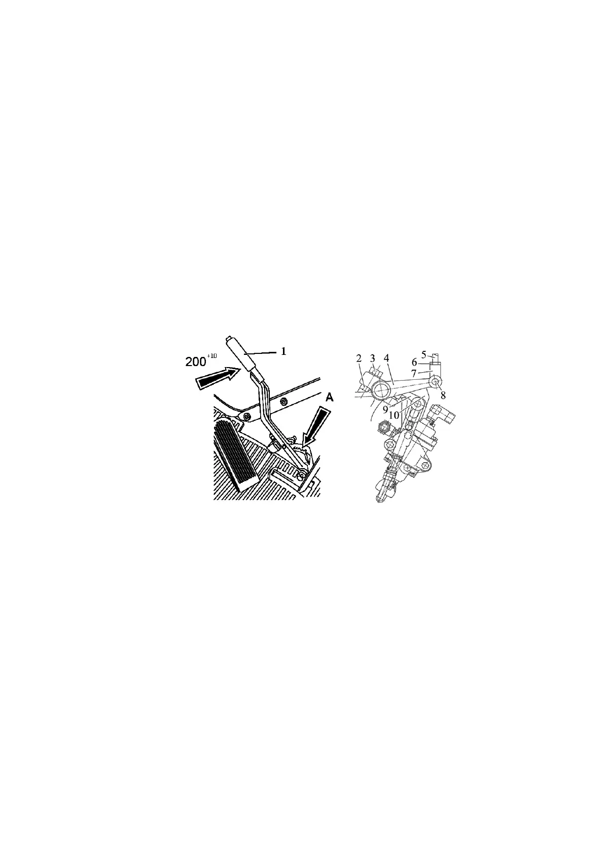
- set parking brake control lever 1 (figure 5.4.36) into the front position (push);
- release locknut 2 of parking brake adjusting bolt 3 as well as locknut 6 of link 5
and remove pin 8;
- turn lever 4 and align the upper edge of the slot of lever 9 and the upper edge of
the slot of lever 10 of the right brake pedal, and then turning yoke 7 align holes of lever 4
and of yoke 7 and put pin 8 in;
- screw adjusting bolt 3 in or out so that, as you pull parking brake control lever 1
with a force of 200 to 210 N, the latch would hold on the second or the third tooth of quad-
rant “A” (which corresponds to the second or the third click as you engage the parking
brake);
- after the adjustment is completed tighten locknut 2 of adjusting bolt 3 and locknut
6 of link 5 with a torque of 75 to 95 Nm.
1 – parking brake control lever; 2, 6 – locknuts; 3 – adjusting bolt; 4, 9 – levers; 5 –
link; 7 – yoke; 8 – pin; 10 – lever of right brake pedal.
Figure 5.4.36 – Adjustment of parking brake control
Final check and adjustment of the parking brake (for tractors with and without pneu-
matic system) shall be carried out on a ready assembled tractor. The tractor shall hold back
on a slope of not less than 18% as you apply the force of not more than 400 N to the parking
brake control lever. If necessary make adjustment by means of adjusting bolt 3.
5.4.4.5 Operation 35. Check of pneumatic system lines for air tightness
To check pneumatic system lines for air tightness, do the following:
- bring the pressure in the pneumatic system to a value of 0.6 to 0.65 MPa (accord-
ing to the air pressure indicator on the dashboard) and stop the engine;
- attach a pressure gauge with a scale division of at least 1 MPa to the connecting head;
- with the help of the pressure gauge make sure that the pressure drop does not ex-
ceed 0.2 MPa within 30 minutes. Otherwise, find out the air leakage spot and eliminate the
fault.
5.4.4.6 Operation 36. Check/adjustment of pneumatic system brake valve actuator
Check and, if necessary, adjust the brake valve actuator as described in subsection
4.7.2 “Check and adjustment of pneumatics brake valve actuator.”