82.3-0000010 OM
193
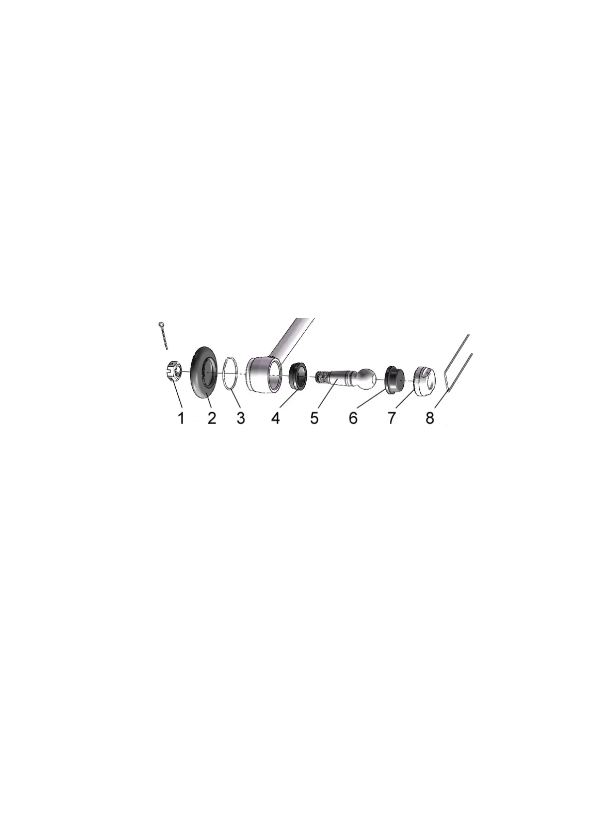
5.4.5.9 Operation 52. Changing grease in steering joints and washing parts of steering
joints
To change grease in the steering joints, do the following:
- remove a cotter pin and unscrew castellated nuts 1 (figure 5.4.54);
- dismantle the steering rod from the axle or FDA levers;
- remove ring 3 and boot 2;
- remove lockwire 8;
- unscrew threaded plug 7;
- remove insert 6, ball pin 5, insert 4;
- wash all parts in diesel fuel;
- apply new grease on the surface of inserts 4, 5 and the sphere of ball pin 5, and also
fill the internal cavity of boot 2 with the new grease, indicated in Table 5.8.1;
- assemble the joint bodies in the reverse order of disassembly. At the same time, to
ensure the necessary tightness in the joint connection, tighten plug 7 so that the ball pin ro-
tates in the sphere when a torque of 6 to 12 Nm is applied;
- lock plug 4 with wire 3;
- install the steering rod on the tractor, tighten castellated nuts 1 with a torque of 100 to
140 Nm and fasten by cotter pin, while unscrewing of the nut is not allowed as the slot of the
nut and the hole of the ball pin align.
1 – castellated nut; 2 – boot; 3 – ring; 4 – insert; 5 – ball pin; 6 – insert; 7 – plug; 8 –
lockwire.
Figure 5.4.54 - Changing grease in steering joints and washing parts of steering joints
Since changing grease in steering joints is technically difficult, grease should only be
changed by dealers.
5.4.5.10 Operation 53. Check and adjustment of pneumatics pressure regulator
Adjustment of the pressure regulator of the pneumatic system must be performed dur-
ing MS-3, as well as in case of malfunction of the pressure regulator and after its disassembly
for washing or replacing worn parts.
Checking and adjusting the pressure regulator of the pneumatic system must be carried
out after performing the adjustment operations for the service brake control, parking brake
control and brake valve drives.
Check the pressure regulator of the pneumatic system as follows:
- connect a pressure gauge (with a division value of 0.01 to 0.02 MPa and a scale of at
least 1.6 MPa) to the connecting head with a red cap;
- remove cap 1 (figure 5.4.55);
- using a wrench, screw cover 2 into the housing until it stops;
- turn on the pneumatic compressor;
- start the engine and fill the cylinder with compressed air until safety valve 7 operates
at a pressure of 0.85 to 1 MPa. If the valve operates at a pressure less than 0.85 MPa or more
than 1 MPa, adjust it using screw 9, first loosening and then tightening lock nut 8.