82.3-0000010 OM
194
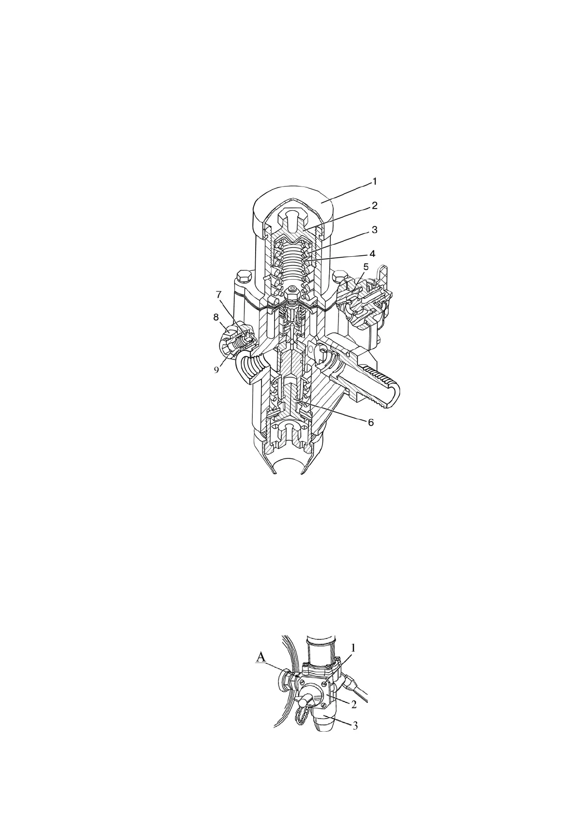
Adjust the pressure regulator of the pneumatic system as follows:
- gradually unscrewing cover 2, adjust the force of springs 3 and 4 so that the air pres-
sure in the cylinder, at which unloading valve 6 opens, is from 0.77 to 0.8 MPa;
- fix this position of cover 2 with paint applied to the threaded part of the body, and put
on cap 1;
- slightly open the condensate removal valve in the cylinder and reduce the air pressure
to a value of 0.65 to 0.7 MPa. At these pressure values, valve 6 should close and switch the
pneumatic compressor to filling the cylinder with compressed air;
- disconnect the pressure gauge from the connecting head.
1 - cap; 2 - cover; 3 - outer spring; 4 - internal spring; 5 - filter; 6 - unloading valve; 7 -
safety valve; 8 - locknut; 9 - adjusting screw.
Figure 5.4.55 – Pneumatic system pressure regulator
Note: the filter is installed only on the regulator 80-3512010. There is no filter on the
other regulators of the pneumatic system.
ATTENTION: IF A FILTER IS INSTALLED ON THE PRESSURE REGULATOR OF
THE PNEUMATIC SYSTEM, THEN CLEANING OF THE FILTER IS REQUIRED EVERY 500
HOURS OF OPERATION (MS-2)!
To clean filter 5 (figure 5.4.55) of air pressure regulator 3 (figure 5.4.56) in the pneumat-
ic system, do the following:
- unscrew bolts 1 and remove cover 2;
- remove the filter cartridge, wash it in cleaning solution and blow with compressed air;
- install the filter cartridge and then the cover, in place.
1 - bolt; 2 - cover; 3 - air pressure regulator in the pneumatic system.
Figure 5.4.56 - Cleaning the filter cartridge of the air pressure regulator filter