Uni-Probe LB 490
BERTHOLD TECHNOLOGIES GmbH & Co. KG
2 – 175
Volume 2 2 Installation
2
Versions for flange shieldings – Rod source with steel cable, one-part or multi-part
– Rod source with shaft core, one-part or multi-part
– Point source with steel cable, one-part
– Point source with shaft core, one-part
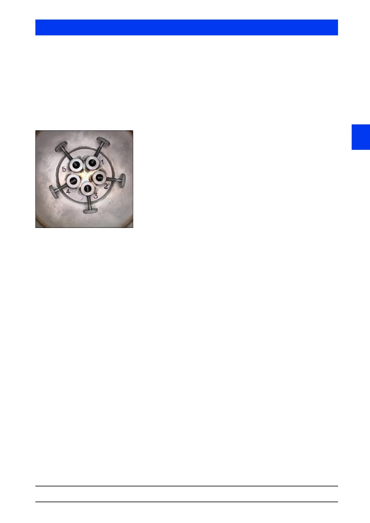
Multi-part rod source flange shieldings can be designed such that
up to 5 rod sources can be installed. Signs are attached on each
steel cable or each shaft core. The signs contain information on
1. the length of the cable for source positioning, if known
2. the source number, e.g. 1860/1-10-08.
The source number consists of several components:
1860 is a consecutive serial number
/1 describes the location of the source in the shielding and thus
allows correlation between steel cable or shaft core and source.
The number is to be found on the sign and also on the head of
the shielding (see illustration to the left).
-10-08 indicates the month and year of production (-MM-YY).
The customer has to provide the protective tube for the source; it
should be installed such that the source can be withdrawn any time
without interrupting the production process. The stability of the
protective tube must match the potential mechanical and chemical
stress.
Depending on the dip tube, it may be necessary to adapt the flange
using a flange adapter. If required and ordered, such an adapter
will be included with the shipment. The dimensions of the adapter
are listed in section 6.11 on page 2–287. Screw material and seal-
ings are not part of the delivery.
In certain applications it is essential that damage to the protective
tubes is detected immediately, so that the source can be secured in
time. Figure 2-35 and Figure 2-36 show installation proposals
which meet the highest safety standards. A double-walled protec-
tive tube is used; the space between both walls is filled with protec-
tion gas and any damage or leak is signaled immediately by a pres-
sure control switch.
 Loading...
