117
Electrical and Ignition
Sensor and Circuit Tests
6
Crankshaft Position Sensor (CPS)
Operation Test
Use the Evinrude Diagnostics software CPS Sync
and engine RPM displays to confirm a valid CPS
signal while the outboard is cranking or running.
An RPM display higher than zero indicates a CPS
signal to the EMM.
Crankshaft Position Sensor (CPS)
Resistance Test
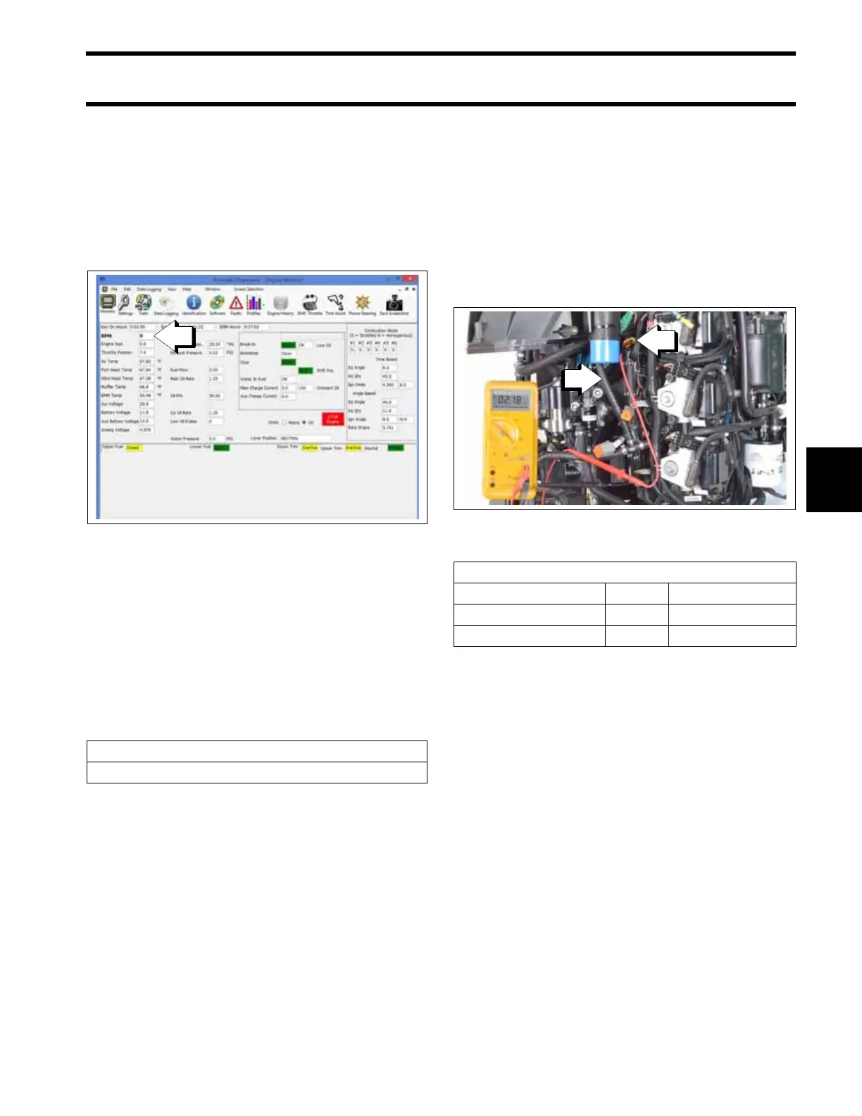
Disconnect the crankshaft position sensor. The
CPS connector is clipped to the cooling water
hose (see following picture).
Use a digital multimeter with appropriate test
probe leads to measure sensor resistance
between the yellow and white wires.
.
The CPS is mounted to the cylinder block and
requires no adjustment. Air gap or clearance to
flywheel is fixed at approximately 0.073 in.
(1.85 mm). The acceptable clearance is 0.036 to
0.110 in. (1 to 2.8 mm).
CPS Circuit Test
Remove the electrical connector from the CPS.
Use a digital multimeter with appropriate test
probe leads to measure sensor circuit resistance.
Make sure the key switch is in the OFF position.
Connect the meter lead to the CPS engine har-
ness connector wire listed in the table. Connect
the negative meter lead to engine ground.
Results:
• An infinite reading (∞) indicates an open circuit.
Isolate the faulty component. Check wiring and
connections. Repair or replace faulty wiring.
Engine Monitor Screen, Engine RPM Display
009242
Sensor Resistance
560 Ω ± 10% @ 77°F (25°C)
1. Cooling water hose
2. Engine harness connector (CPS)
009353
CPS Circuit Resistance
Wire Pin Result
YELLOW 1 2000 Ω ± 300 Ω
YELLOW/WHITE 2 < 1 Ω